Here's a little side project, and it comes with Eagle Project files so you can order, etch and modify it anyway you like. All project files are available on this Hackaday.io project page: https://hackaday.io/project/18624-muffsy-constant-current-led-tester
LEDs seem to accumulate. They're scattered around, some don't work, some are blown, most of them are transparent so there's no way of knowing which color they are.
In addition to just testing my LEDs, I'd also like to adjust the brightness and find the forward voltage drop. All using something that won't break any more LEDs, no matter what I do.
I've been working with the LM317 (and others) voltage regulator, and noticed that it can be used as a constant current source. LEDs are driven by current, not voltage, so this is a great advantage in several ways:
- I don't have to worry about how high the input voltage is
- I don't have to take the forward voltage drop is
- Limiting the current ensures that the LEDs are not destroyed if the polarity is wrong
- The current and voltage can be measured and used in any circuit
Before I get to the circuit, here's how to use the LED-tester to decide the resistor value needed for a certain brightness:
- Place an amperemeter in series with the LED in the LED tester. This will give you the current. Let's say it's 10 mA.
- Place a voltmeter in parallel with the LED in the LED tester. This will give you the forward voltage drop. Let's say it's 1.8V
- You want to place this LED, at this brightness in a circuit with 15V.
- The voltage is your circuit voltage minus the forward voltage drop: 15V - 1.8V = 13.2V
- You can now find the resistor value using Ohm's law, R = U / I: R = 13.2V / 0.01 A = 1.320 ohms
- A 1k3 ohm resistor will be suitable for this LED when it's powered by 15V.
.png)
The circuit works as follows:
- Power it with a 9V battery
- The LM317 will maintain 1.25V between the Output and the Adjust pins
- Place resistors between these two pins, and you can regulate the current
- Use one fixed resistor to set the maximum current
- Use a potentiometer to adjust the current from maximum to minimum, LOG or LIN
- Use a suitable connector for the LED under test, 5/5.08 mm screw terminals will fit directly on the board
- Place a voltmeter in parallel with the LED under test, this will give the forward voltage drop
- Place an amperemeter in series with the LED under test, this will give the current
Oh, there's always one more thing. The LM317 will stop regulating under 2-3 mA. Since high intensity LEDs often can require less than 1 mA to reach the desired brightness, we'd like to go down to below those 2-3 mA.
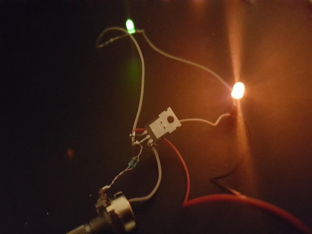
To make sure there's always enough current drawn from the voltage regulator, place a power-on LED from its output to GND. In this circuit, it draws approx 4 mA.
Here's the PCB layout. Using a LOG pot will give better response within the low current region, a LIN pot gives better response at higher current.
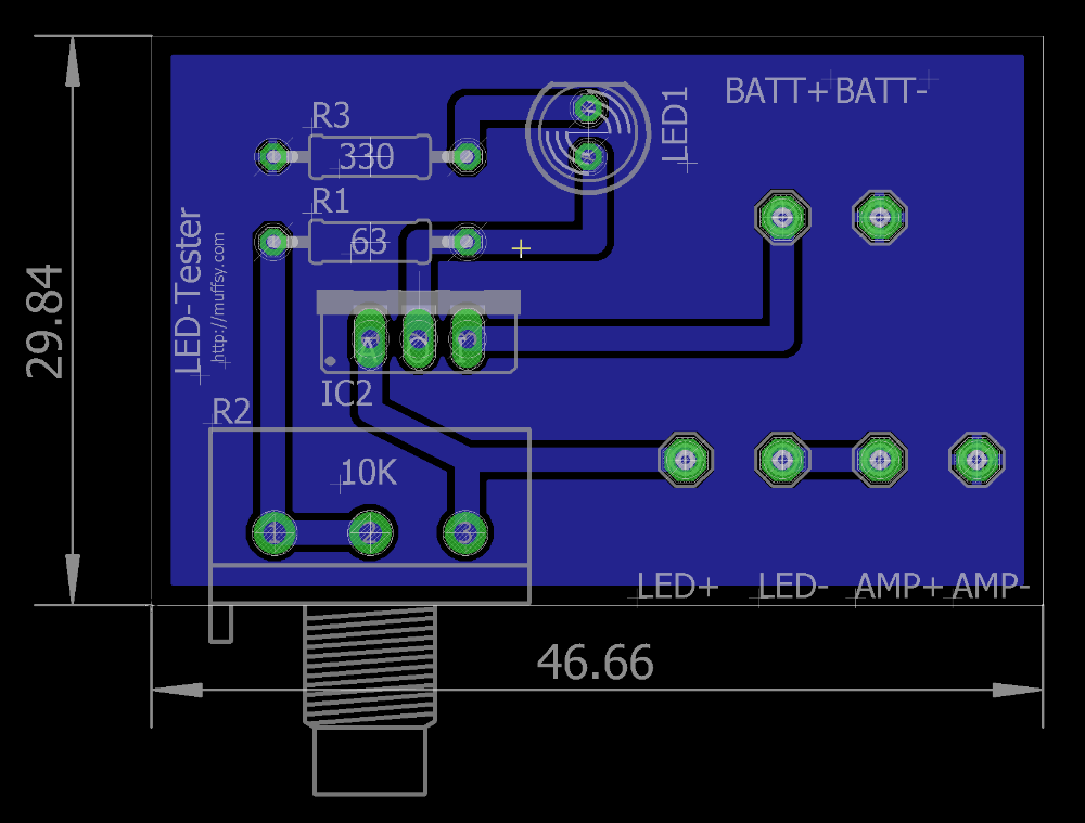
The dimensions of the board above are in millimeters. The Eagle project files are available here: https://hackaday.io/project/18624-muffsy-constant-current-led-tester