Build the Muffsy MC Head Amp MH-1
This kit is for sale on Tindie:
https://www.tindie.com/products/skrodahl/muffsy-mc-head-amp-kit/
The Muffsy MC Head Amp kit comes complete with all on-board components. Read these instructions carefully before you start building, then follow each step when building the kit.
You can also have a look at the schematics for the Muffsy products under the Modify It page.
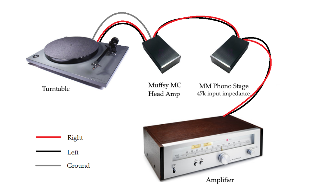
Connecting the Muffsy MC Head Amp
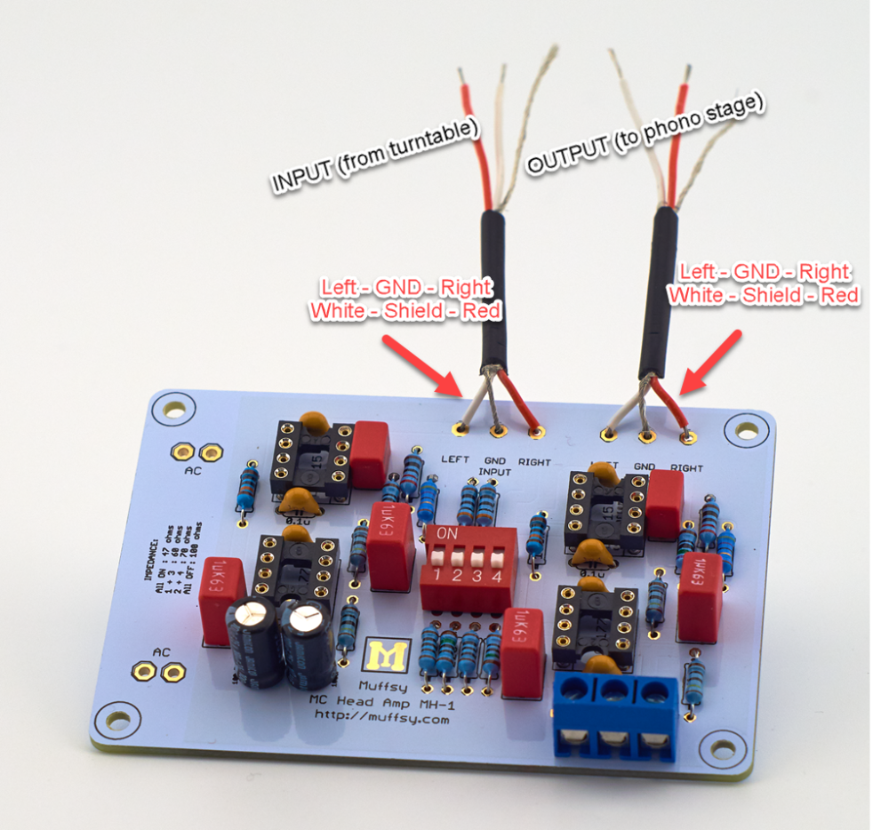
This is how you connect your Muffsy MC Head Amp when you're done building it:
Before You Begin Construction
PLEASE NOTE:
- Make sure you have time to construct the kit. If you are stressed, building the kit will not be very rewarding. And it often leads to mistakes.
- Familiarize yourself with the instructions before you start building the Muffsy MC Head Amp.
- Even if you're not using the Muffsy Power Supply, Back Panel or the B0905 cabinet, the information given here will serve as inspiration for your build.
- Do perform the tests in Step 14, so you don't risk damaging your head amp.
- It's not recommended to use batteries to power the Muffsy MC Head Amp.
- Wash your hands carefully afterwards if you're using leaded solder. Do not lick your fingers or touch any food items while working.
Ready? Here we go!
Illustrations Explained
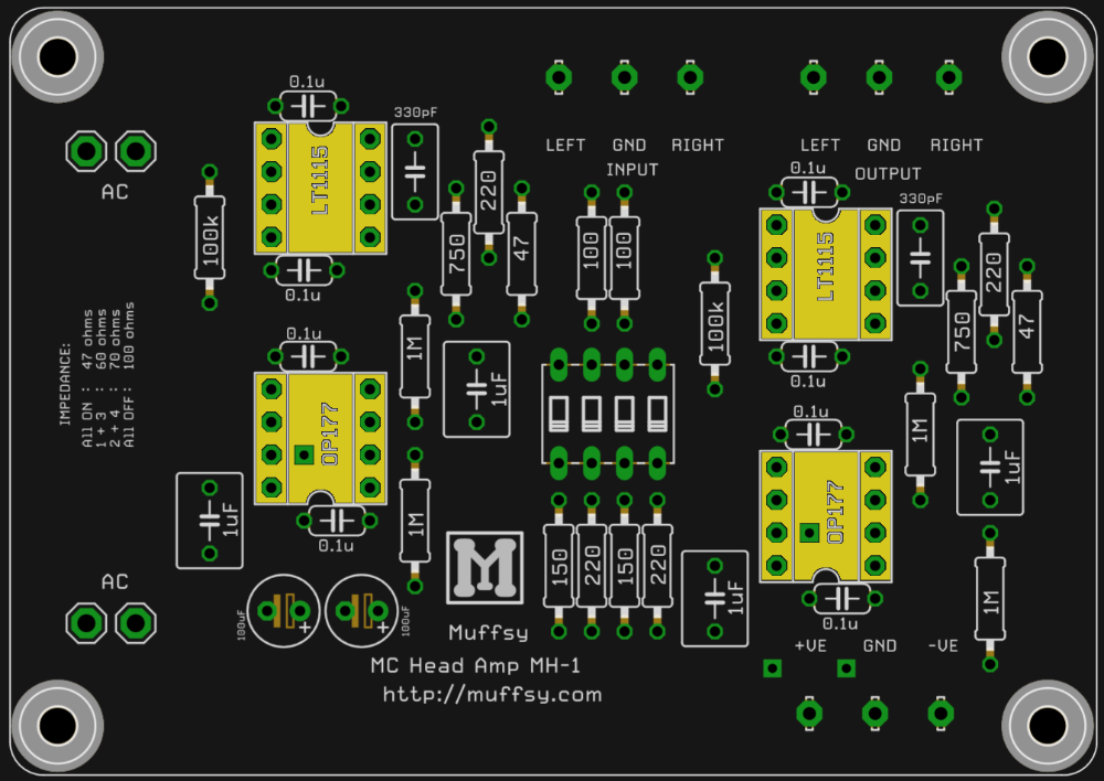
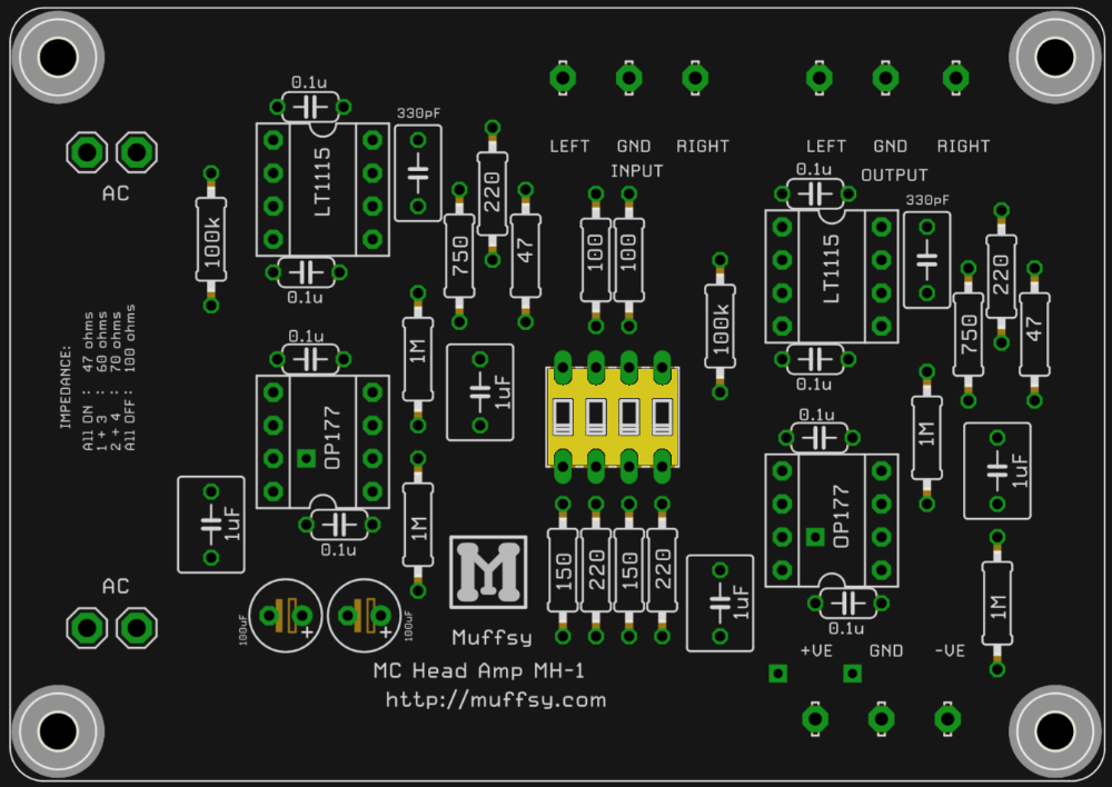
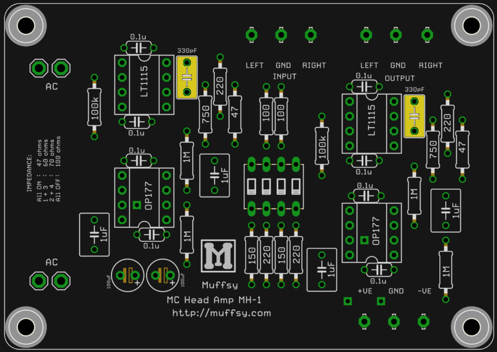
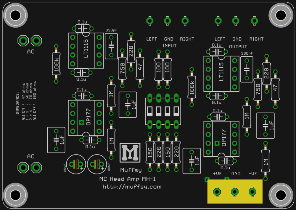
The picture below is a larger version of your printed circuit board. For each step, this will be used to show you which components you will be adding to the board.
.png)
This picture shows you where you are in the build process. It also shows what each component looks like, and it will contain special instructions or information.
Step 1 - Check the Kit Contents
Before you start building, check that you have all components and familiarize yourself with the kit. Here's a list of the kit's contents:
| Quantity | Component |
|---|---|
| 1 | Muffsy MC Head Amp, Printed Circuit Board |
| 2 | Resistors 0.25W, 47 ohm |
| 2 | Resistors 0.25W, 100 ohm |
| 2 | Resistors 0.25W, 150 ohm |
| 4 | Resistors 0.25W, 220 ohm |
| 2 | Resistors 0.25W, 300 ohm |
| 2 | Resistors 0.25W, 750 ohm |
| 2 | Resistors 0.25W, 100k ohm |
| 4 | Resistors 0.25W, 1M ohm |
| 2 | Film capacitors, 330 pF |
| 8 | Ceramic capacitors, 0.1 uF |
| 4 | Film capacitors, 1 uF |
| 2 | Operational amplifiers, LT1115 |
| 2 | Operational amplifiers, OP177 or OPA177 |
| 2 | Electrolytic capacitors, 100 uF |
| 1 | Four-way DIP-switch |
| 4 | 8-pin DIL sockets |
| 1 | Screw terminal, 3 positions |
| 1 | Sticker with alternative impedance values |
| 30 cm / 1 ft | RVVP 2x0.2 shielded audio cable |
Note:
This high quality printed circuit board has plated-through holes. Do not attempt to drill the holes to make them larger, doing so will destroy the board. The four mount holes, one in each corner, may be drilled to size.
Step 2 - Solder the Resistors
There is a total of 18 resistors that go onto the printed circuit board. The resistors are bidirectional, meaning that you don't have to worry about which way they are oriented.
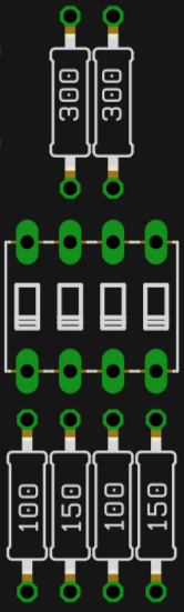
- Before you solder the resistors, consider if you want to change the input impedances using the resistors included in the kit. Here's how you can do that.
- See the picture below for where to place the resistors, depending on which input impedance scheme you have chosen. Apply the included sticker if you decide to use the alternative impedances:
.png)
.png)
All orders after 2016-09-28 are shipped with resistors that will let you choose between these two input impedance schemes. When you're done, you will end up with either 2x 220 ohm or 2x 300 ohm resistors that are left over.
- You may want to lower the gain. Replace the 47 ohm resistors with 82 ohm (not included in the kit) to get 5 mV output from a 0.5 mV cartridge. The default setup gives:
- 0.15 mV input = 2.5 mV output
- 0.3 mV input = 5 mV output
- 0.5 mV input = 8.5 mV output.
It's recommended that you measure the resistors before you put them in place, and make absolutely sure that the right resistors go in the correct positions.
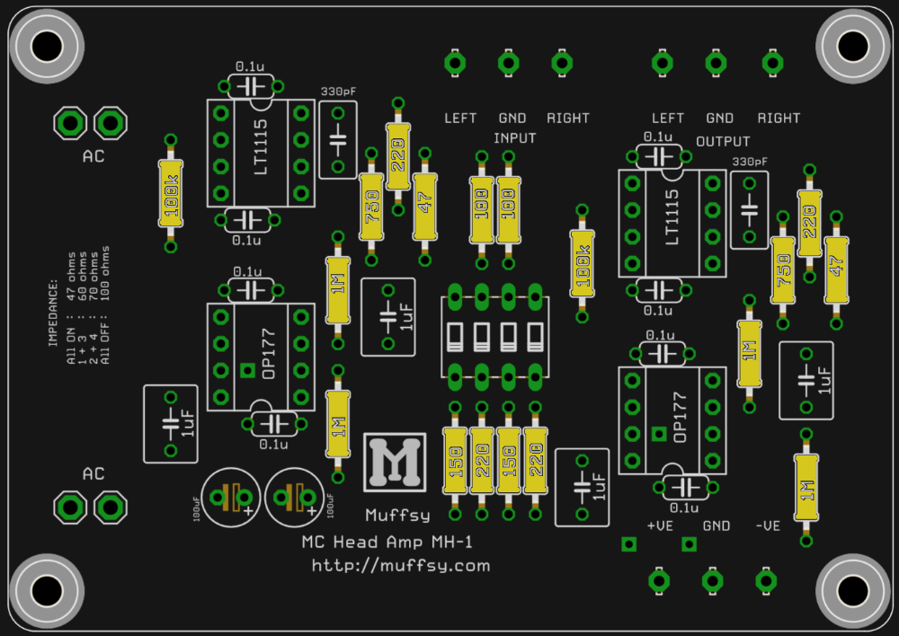
The picture below shows all the standard resistors soldered in place. The resistors in the kit are Multicomp MF25, 1% tolerance with a temperature coefficient of ±50ppm/°C. They are very fit for the job, and you should not have to worry about replacing them with more audiophile resistors.
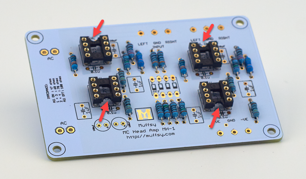
Step 3 - Solder the DIL Sockets
These are the sockets for the operational amplifiers, and there are four of them. They will make it easier to replace the small chips later on if you should want to. Soldering the sockets will also make sure you don't overheat the operational amplifiers when installing them.
The orientation is very important for these four sockets, get it wrong and you will be confused about which way to mount the operational amplifiers. There's a notch in the socket that matches up with the picture on the printed circuit board, as shown in the pictures below.
Note that the text beneath the DIL sockets refers to the operational amplifiers that will be mounted later.
Using a piece of masking tape to hold the sockets in place might be a good idea.
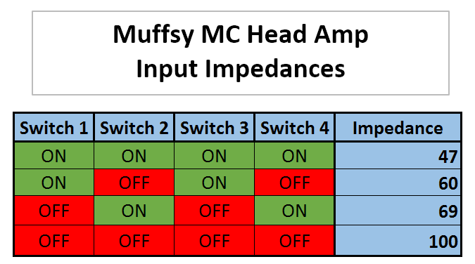
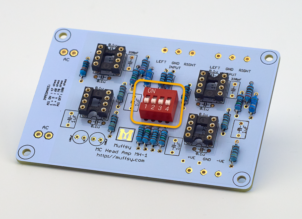
Step 4 - Solder the DIP Switch
This four-way DIP-switch is here to adjust the input impedance of the head amp.
It is absolutely essential that you get the orientation right. If you don't, adjusting the features of the head amp will be very difficult and confusing. The text "ON DIP" goes towards the top of the board and the numbers "1 2 3 4" go towards the bottom, as shown in the photo.
Use a piece of masking tape to hold the switch in place while you solder.
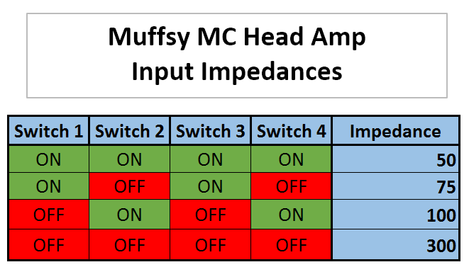
The input impedance can be set between 47 and 100 ohms, or between 50 and 300 ohms (alternative resistors) in four steps, according to the tables below (and the text on the board itself).
The safest choice is to set the impedance to 100 ohms, unless you know exactly which impedance your cartridge needs.
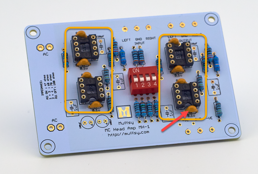
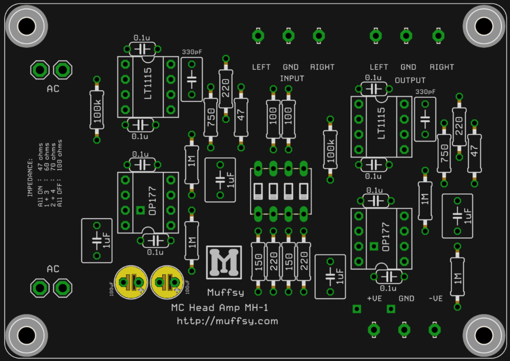
Step 5 - Solder the Ceramic Capacitors
The eight ceramic capacitors shown in yellow in the picture below are up next.
They don't need to be oriented in any special direction. It's a good idea to mount them with the text outwards though, so that the values are visible.
.png)
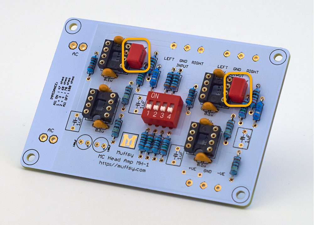
Step 6 - Solder the 330 pF Capacitors
These are Wima FKP2 polypropylene capacitors. There's two of them, one for each channel. Mount them as shown on the pictures below, orientation does not matter.
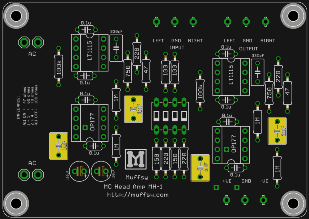
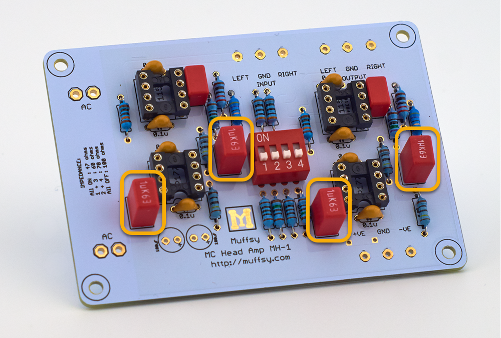
Step 7 - Solder the 1 uF Capacitors
These four larger capacitors are Wima MKS2 polyester models. There's four of these capacitors. Orientation does not matter, although it looks nicer if they're all mounted the same way. These pictures show where the capacitors go.
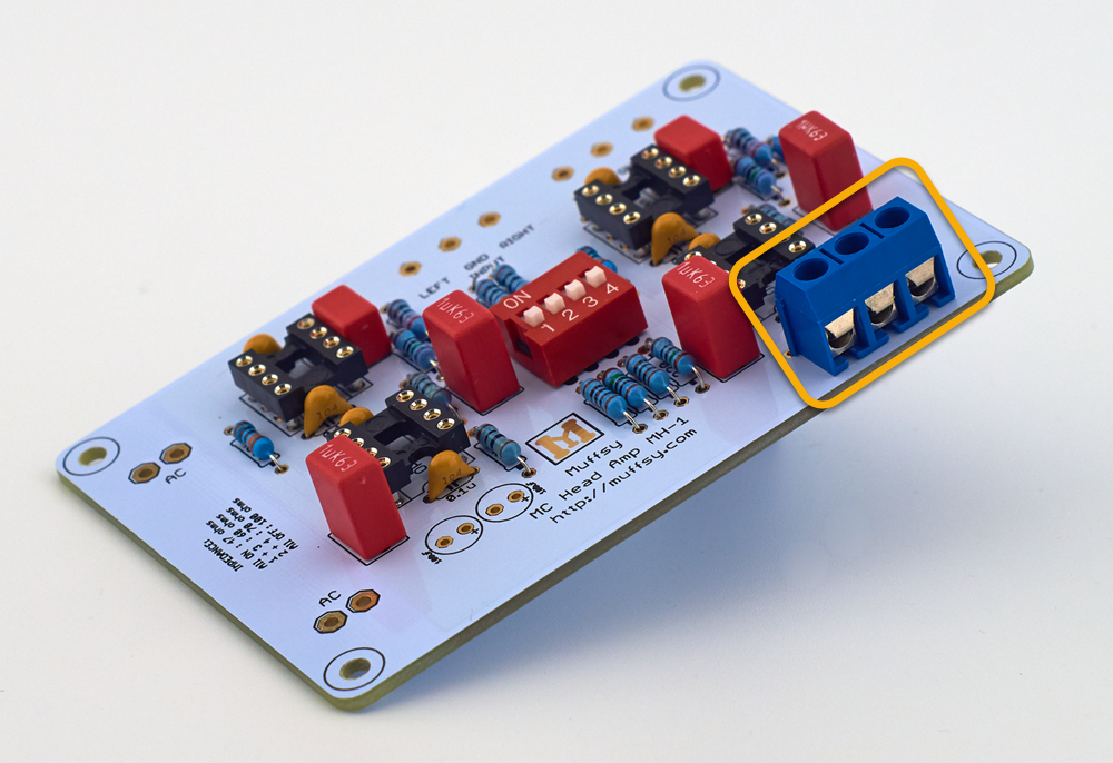
Step 8 - Solder the Screw Terminal
The kit contains one screw terminal with three inputs that connects to the power supply. There is space for screw terminals on the signal input and output, but these really should be soldered directly to the board in order to avoid introducing noise into the circuit.
Solder the screw terminal as shown in the pictures below.
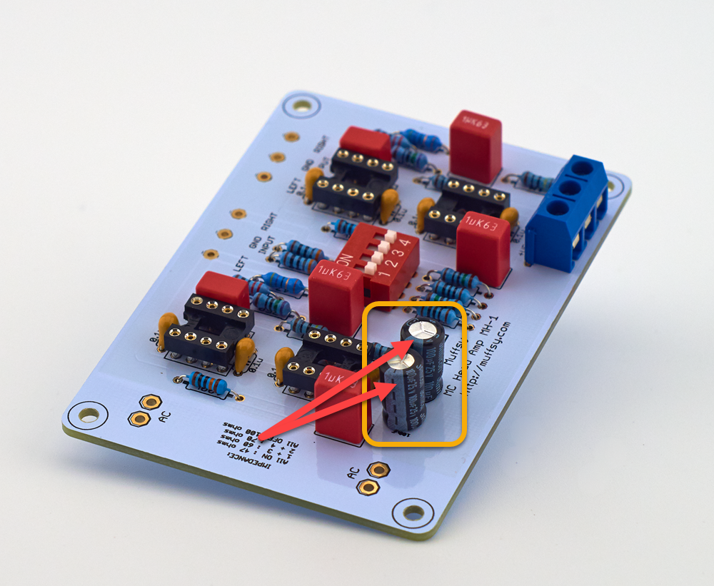
Step 9 - Solder the Electrolytic Capacitors
These two electrolytic capacitors form the power supply decoupling together with the ceramic capacitors in step 5.
Please make sure that they are mounted correctly, or they can go "poof". The longer leg goes in the hole marked '+', the shorter leg (which has the white strip with the '-' symbols) is oriented to the left, when the board is seen as it is below. The second picture shows how it should look when you're done.
Step 10: Build the Power Supply
Follow the build instructions for the Muffsy Power Supply v4.
PLEASE NOTE: Make sure that you don't exceed the maximum voltage of your operational amplifiers. The Muffsy Power Supply delivers +/- 15 volts, which is fine for the op amps delivered with the kit. Others, like certain discrete operational amplifiers, max out at +/-12 volts. (Have a look here if you need to change the Muffsy Power Supply's voltage.)
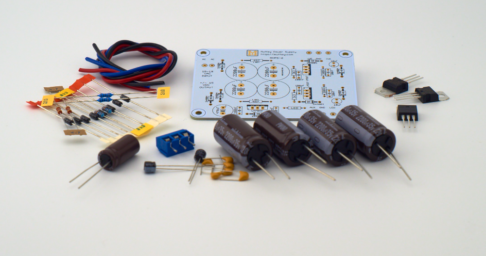
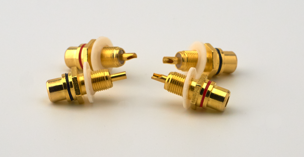
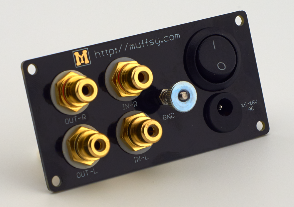
These are all the parts you'll need for the back panel, all of them are included in the back panel kit:
.png)
Take the four RCA connectors and put the plastic shims on them. The plastic shims on the front can be left out, but you will find that the connectors are easier to tighten with the shims though.
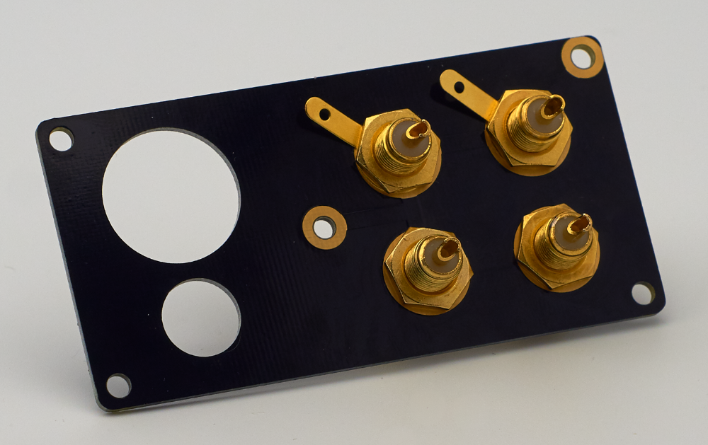
Mount the two RED connectors in the top holes, and the two BLACK connectors in the bottom holes:
.png)
Insert the ground pads on the top two connectors and fasten them with a nut. Fasten the bottom connectors with nuts only.
It's a good idea to use a couple of wrenches to make sure the RCA connectors are tightly fastened. If they are loosened and twisted around, you could snap or short the signal cables connected on the back of the connectors.
PLEASE NOTE:
These connectors are electrically connected together inside the back panel, do not use the plastic shims on the back. If you do add these shims, you will get humming and poor sound quality.
Mount the ground screw and fasten it with a nut. Add the shim and the knurled thumb nut:
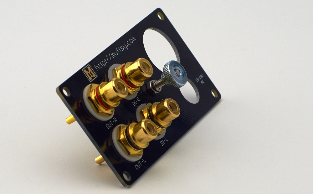
Mount the power connector. The hole is not centered, make sure it is towards the top of the board. Fasten the power connector with the nut that comes with it:
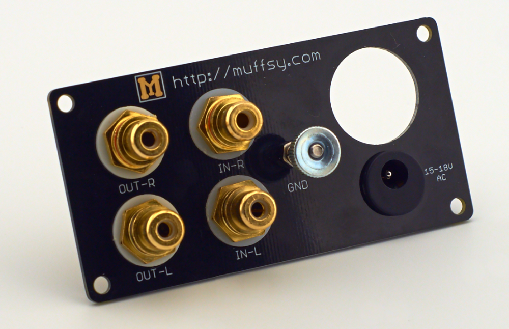
Click the power button in place. Make sure the "1" is on top:
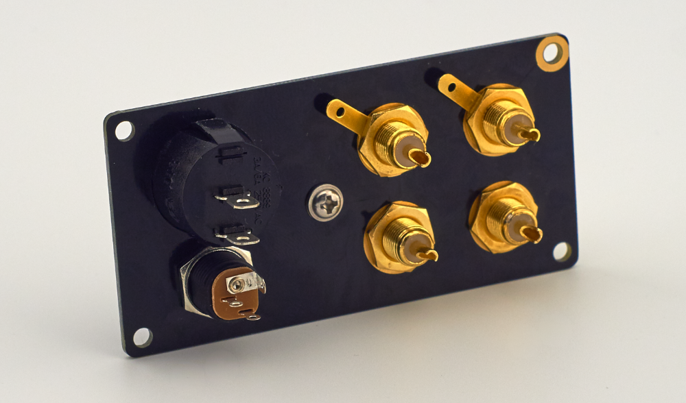
Your back panel is now done. Here's how the backside looks when it's finished:
The information below is for the Muffsy MC Head Amp, Muffsy Power Supply and Muffsy Back Panel mounted in a B0905 cabinet.
You may want to do this in an entirely different way if you don't have all these components, if you want to incorporate the Muffsy Phono Preamp, or if you want to use a different enclosure.
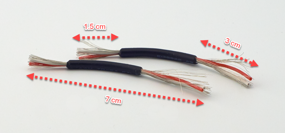
Cut two pieces of the shielded audio cable, approx 7 cm long. Strip the wires as described below:
- 3 cm at one end (this end connects to the back panel)
- 1.5 cm at the other end (this end connects to the phono preamp's in- and outputs)
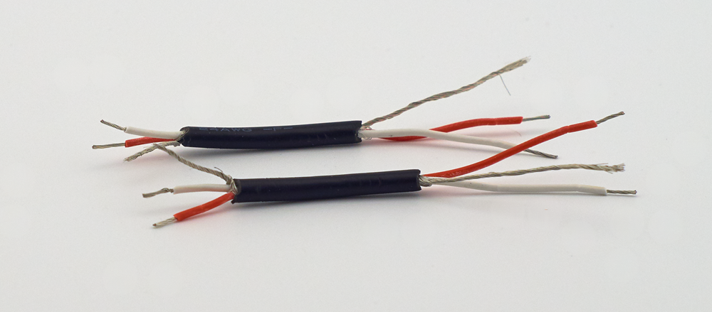
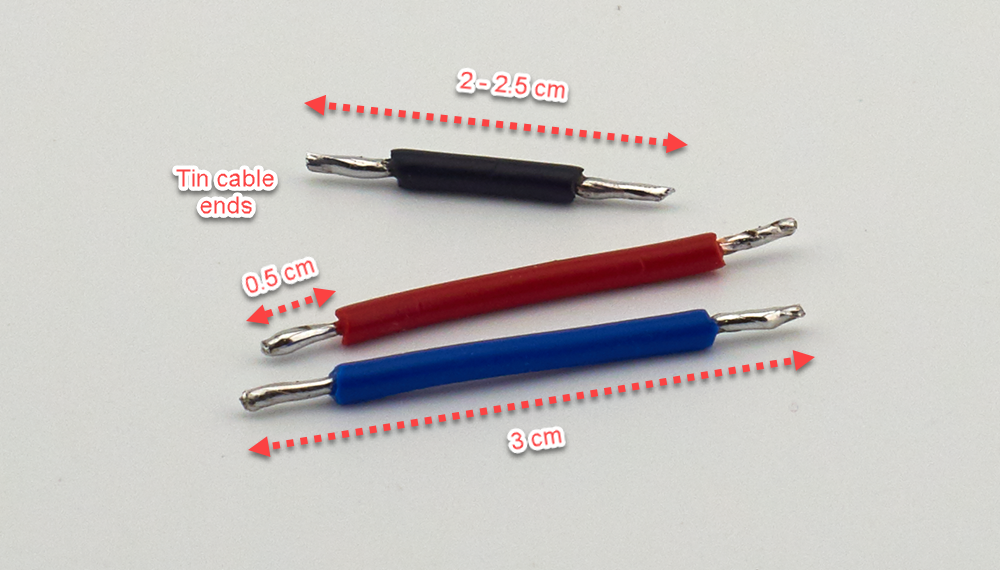
When you're done, the cables will look like this:
Twist the shielding (the exposed outer wire) and strip about 0.5 cm from each of the red and white wires. Twist the ends tightly.
Solder the 1.5 cm ends into the inputs/outputs on the Muffsy MC Head Amp board. Soldering, instead of using screw terminals, will make a better signal connection. This is very important when dealing with sub-microvolt signal levels.
- IN-L / OUT-L: White
- GND / GND: Shield
- IN-R / OUT R: Red
Cut one piece of black wire to about 2 - 2.5 cm, two pieces of red and blue wire, and strip about 0.5 cm on each end. Tin both ends of each cable:
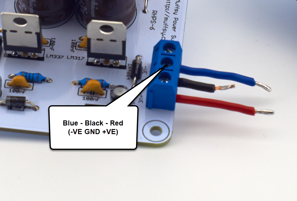
Connect the tinned end of these three wires to the power output screw terminal on the Muffsy Power Supply.
- Blue cable goes in the top hole (-VE)
- Black cable goes in the middle hole (GND)
- Red cable goes in the bottom hole (+VE)
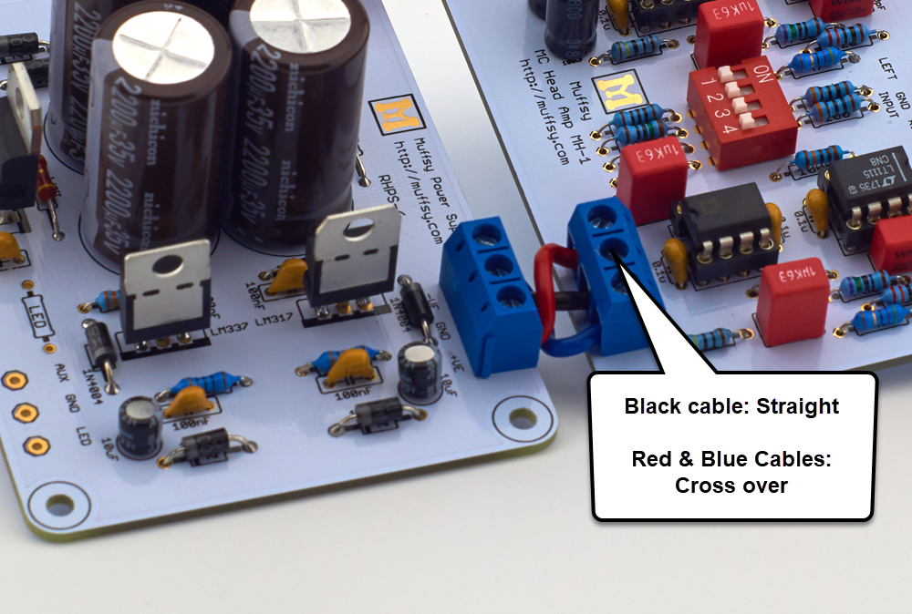
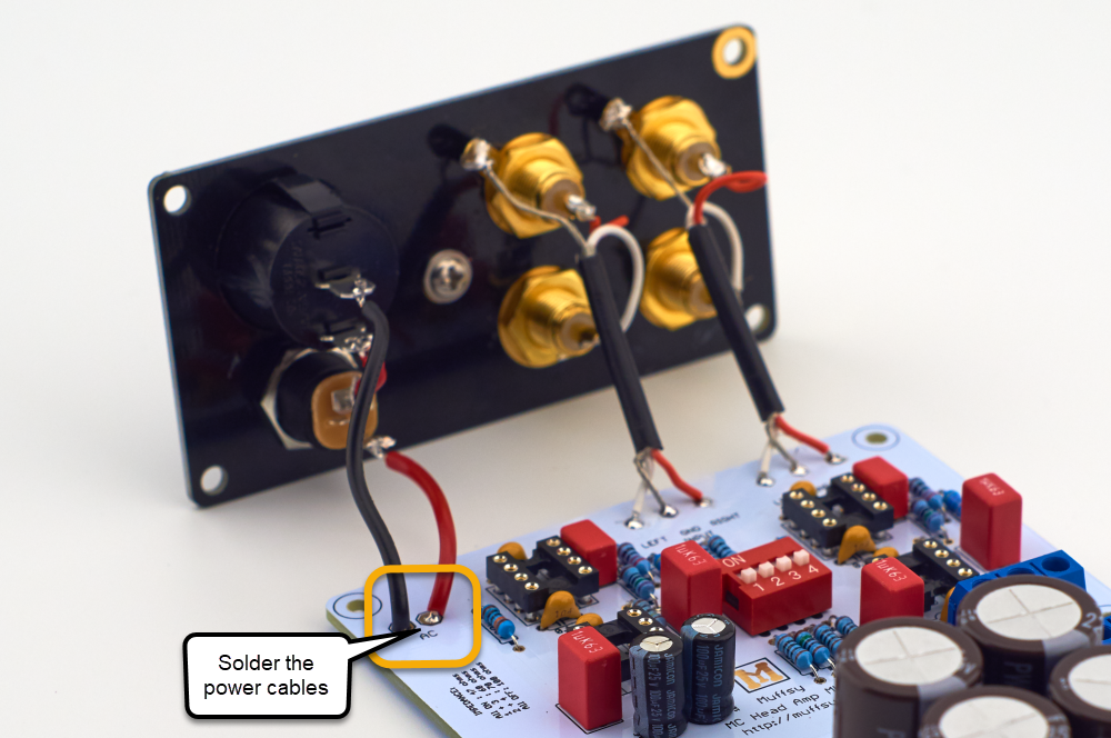
Stick the other end of these three power cables into the MC Head Amp Board, crossing over the red and blue ones, and fasten the screws.
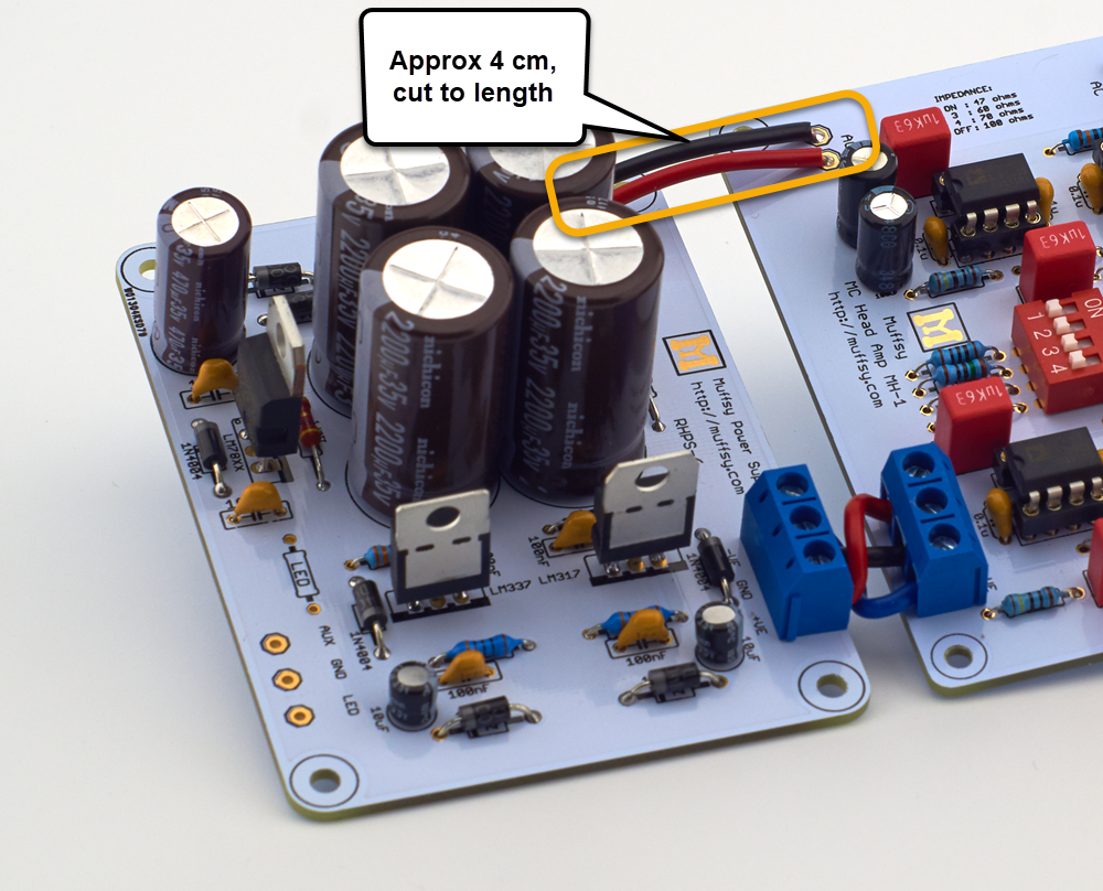
Cut a red and a black piece of wire to size, approx. 4 cm (these may need to be shorter or longer, place your cables over the boards and cut to the length that suits your assembly), and connect the two boards as shown below. It does not matter which color goes where.
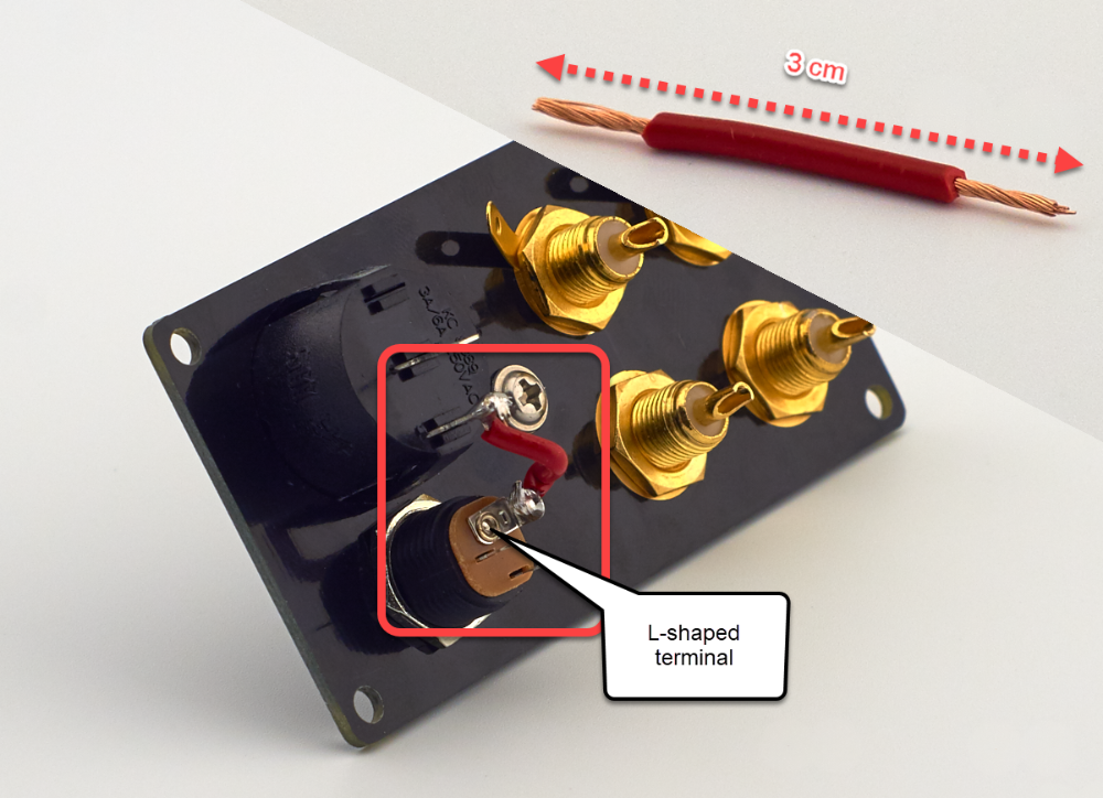
Cut a piece of red wire, ~3 cm, and strip 0.5 cm from each end.
Solder this wire between the bottom of the back panel's power button and the L-shaped terminal on the power connector.
PLEASE NOTE: Take care not to apply too much heat to the connectors on the power button. The plastic could melt otherwise. (I've used 330 degrees C / 625 degrees F).
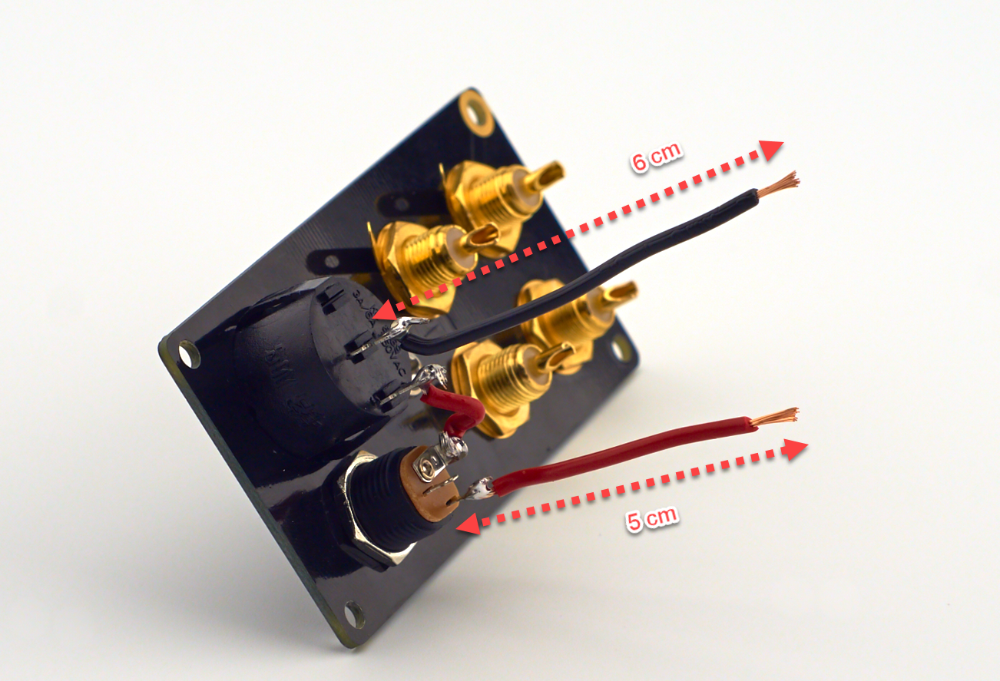
Cut two cables. Red = 5 cm and Black = 6 cm.
Strip ~0.5 cm from both ends of both cables, solder the shorter red cable to the bottom terminal on the power connector (the next one, clockwise from the L-shaped terminal).
Solder the black cable to the upper terminal of the power button, making sure not to overheat it. (Again, I've used 330 degrees C / 625 degrees F).
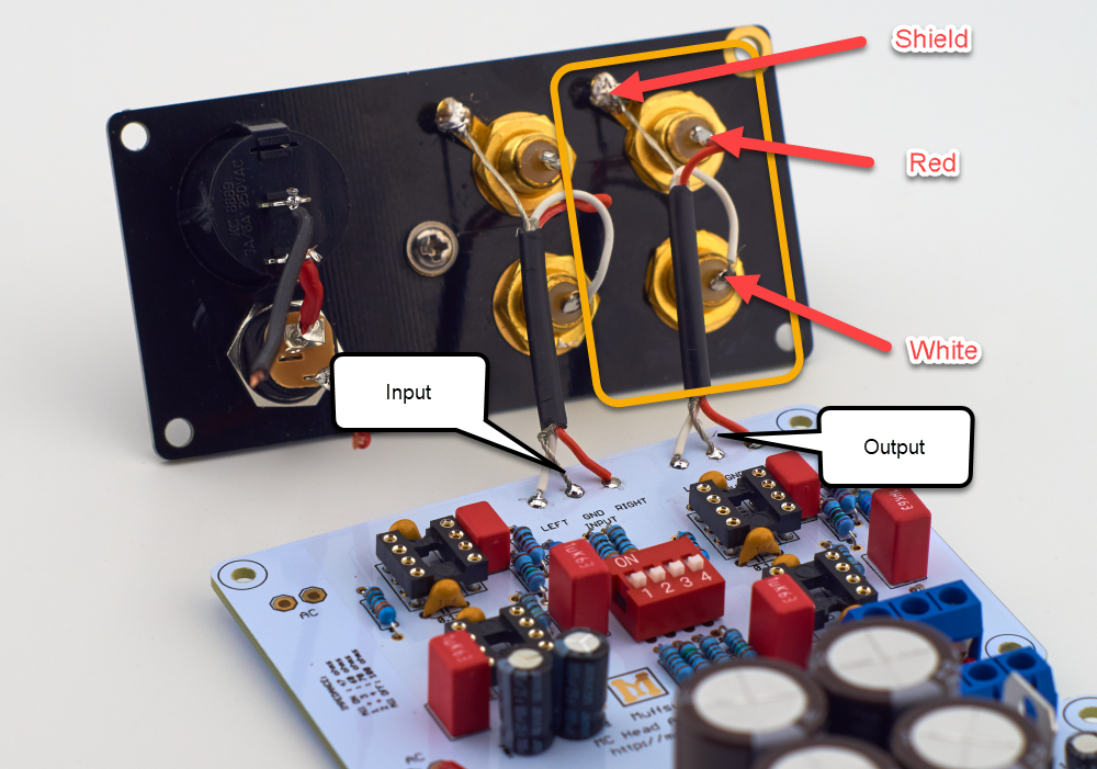
Solder the input and output signal cables to the back panel.
GND Terminal: Shield
Top RCA: Red
Bottom RCA: White
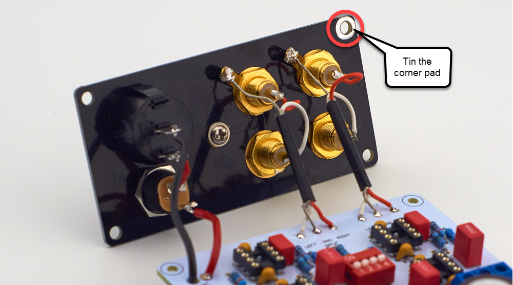
Solder all of them, aligned with the back panel as shown below:
Solder the red and black power cables from the Muffsy Back Panel to the Muffsy MC Head Amp. It doesn't really matter which cable goes where, it does look nicer if it matches the cables from the Muffsy MC Head Amp to the Muffsy Power Supply though.
Finally, dab some solder on the corner pad on the Muffsy Back Panel. This will help ground and shield the entire head amp later on.
Use just a small amount of solder and smear it around the pad.
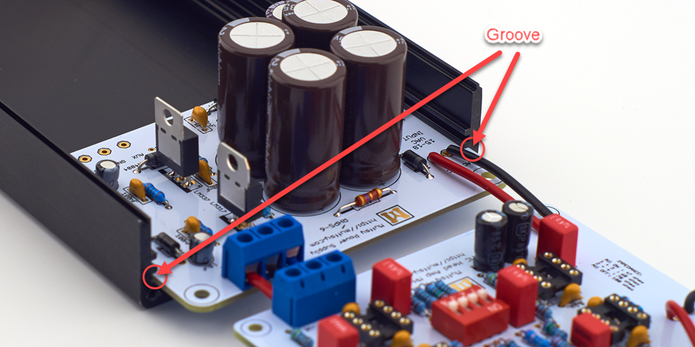
Step 13: Mount the Muffsy MC Head Amp in the B0905 Cabinet
Mounting the Muffsy MC Head Amp in the B0905 cabinet couldn't be easier. Just slide the boards into the grooves of the cabinet, starting with the Muffsy Power Supply.
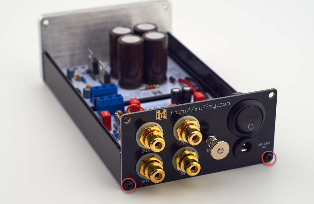
Screw the back panel in place, using the provided screws.
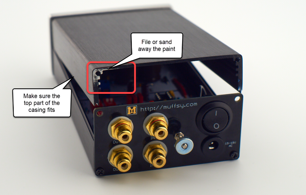
Test fit the upper part of the enclosure to see which way it fits. File or sand away the paint from the upper left corner.
This is where the tinned ground pad on the Muffsy Back Panel connects to the enclosure.
Testing the Muffsy MC Head Amp before using it is essential. If these tests are not successful, it's very likely that you will damage the operational amplifiers.
You will need a multimeter capable of measuring both AC and DC volts for these tests.
Do Not Use Battery Power - Make Sure All the Voltages are Correct
The OP177 operational amplifiers are there to make sure that there is no DC offset on the signal. If there is only one of the voltages present, +15 volts or -15 volts, they will work very hard to correct this, frying your LT1115 operational amplifiers in the process.
If you're using batteries, this can happen if only one of them runs out of power. This is why you're discouraged from using batteries to power your Muffsy MC Head Amp, and why you need to be 100% sure that the voltages are correct.
Before you go ahead, you should visually inspect the circuit boards.
- Make sure all the components are mounted, and that the orientation is correct
- See if all component leads are soldered, and check for bad solder joints or shortcuts between the joints
- Cut all leads underneath the boards so that they are flush with the solder joint
- Check that no leads on either sides of the boards are touching each other
- Double-check all the connections between the boards and to the back panel
- Don't let the bottom of the boards, or the component leads touch the enclosure
Remove the Operational Amplifiers
If you have installed the operational amplifiers in their sockets, please remove them. The purpose of this test is to make sure that they're not being damaged.
Turn the Power to OFF, and Connect the AC Adapter
Turn the Power ON
This is your very first test. Turn the power button ON, and touch the components on the Power Supply to check that they don't get hot.
If any of the components get hot to the touch, there's something wrong with your power supply or cabling. Remove the power adapter immediately and check the power supply board for errors.
If the components stay cool, move on to the next step.
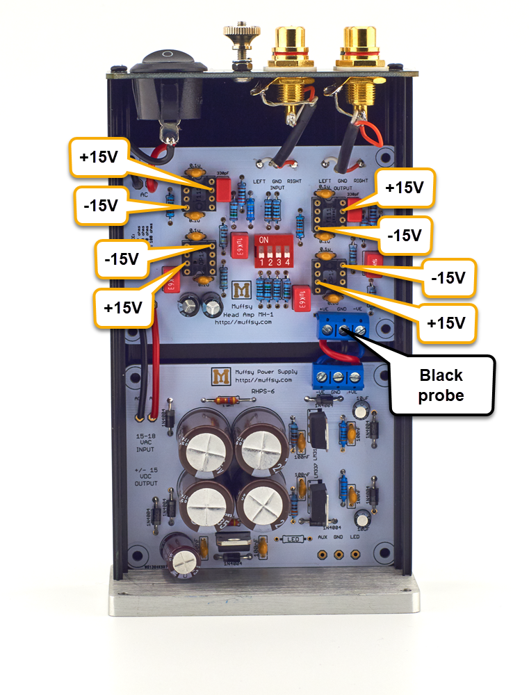
Measure the Muffsy MC Head Amp Board
- Take out your multimeter, turn it to VOLTS DC and place the BLACK PROBE on the middle screw on the screw terminal
- Place the RED PROBE on each of the "+15V" and "-15V" spots marked on the picture below, and check the voltage
- The voltages are never exactly 15 volts, but they will be very close
- If the voltages are correct, you can move on to installing the operational amplifiers
- If the voltages are incorrect, repeat the inspection again
- If you can't find anything wrong from the inspection, look below for more options
Troubleshooting
These are the errors you can get:
- All the tests show ZERO volts
- All the "+15V" test points show ZERO, or very close to ZERO volts
- All the "-15V" test points show ZERO, or very close to ZERO volts
- The test points show some other voltage
Make sure you have an AC power adapter:
- You should use a power adapter from 15 to 18 volts, and it needs to have AC output, usually marked "AC to AC", "AC/AC" or using the symbol "~"
- If the power adapter says "AC to DC", "AC/DC" or has the symbol "=", it is a DC adapter and needs to be replaced with an AC adapter
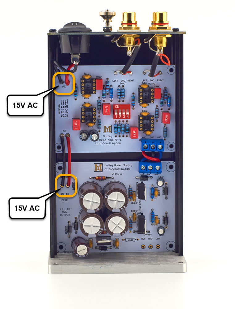
Check that the power supply is getting power:
- Set your multimeter to VOLTS AC, and measure across the input screw terminal on the power supply (marked in the picture below)
- The voltage should be at or above what it says on the AC adapter
- If you measure zero volts, change your multimeter setting to VOLTS DC
- If you measure either +15 volts or -15 volts DC, or more, you are using a DC adapter. Replace it with an AC adapter
- If you still measure zero volts, check the wiring from the power connector, through the power switch, through the AC traces on the Muffsy MC Head Amp and to the power supply
- If the connections are okay, make sure that your AC adapter is working
- If the power supply is getting AC-power, and the output power is missing or wrong, you need to go back and inspect your board. Make sure that the orientation and placement of the components are wrong. Things to look out for is placement of voltage regulators, and orientation of diodes and electrolytic capacitors. Check that all the solder joints are okay, and that there are no short circuits anywhere.
Internal Phono Stage
If your turntable has a built-in phono stage, make sure it's turned off.
The output from the Muffsy MC Head Amp needs to be connected to a phono stage for MM cartridges. That could be the Muffsy Phono Preamp, or your existing phono stage.
Support
If you have gone through all the tests and the troubleshooting, and your Muffsy MC Head Amp still isn't working, please contact me so we can find and fix the problem together.
Before you mount the operational amplifiers, disconnect the AC adapter and turn the power switch to OFF. If you don't, the op amps may be damaged.
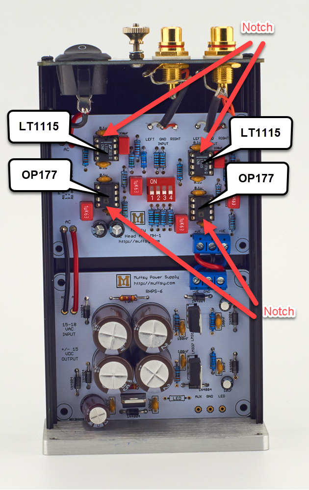
There are four operational amplifiers in the kit. Two marked LT1115 and two marked OP177. The LT1115s do the amplification and the OP177 make sure that you don't have any DC in your signal.
Mount the operational amplifiers in their sockets, as shown in the picture below. The sockets and operational amplifiers have a notch that correspond. Insert the op amps carefully into their sockets without bending any of the legs, and check that the orientation of each chip is correct. Mounting them wrong will most likely damage them.
Connect the AC adapter and turn on the power, while touching the LT1115 operational amplifiers.
If the LT1115 op amps get really hot, disconnect the power immediately, and go through all the tests again. The LT1115 operational amplifiers will get a little bit warm when the head amp is powered on, but they should not be burning hot.
Congratulations, You Have Built the Muffsy MC Head Amp!
Here's a few parting words before you enjoy your new Muffsy MC Head Amp:
- The Muffsy MC Head Amp is only to be used with low output MC (LOMC) cartridges
- Connect the cables from your turntable to the input of the Muffsy MC Head Amp, and make sure the ground cable is connected at both ends
- The Muffsy MC Head Amp does not apply any RIAA correction, it needs to be connected to an MM phono stage, like the Muffsy Phono Preamp
- Tell all your friends, family, colleges and random strangers on the street about your Muffsy, and write about it on the forums you subscribe to
- An honest review on Tindie is always greatly appreciated. Do contact me first in case you have any complaints though, and we'll make sure your head amp is working to your satisfaction