Build the Muffsy Hifi Dual Power Supply
Please note that the Muffsy Hifi Dual Power Supply is delivered as a printed circuit board only. You need to buy the components listed in the bill of materials below.
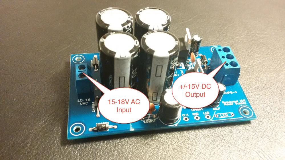
A 15-18 volts AC wall adapter is needed to make this power supply work. Here is some more information about what you need to build the Muffsy Phono Preamp and Power supply.
You can also have a look at the schematics for the Muffsy products under the Modify It page.
Illustrations Explained
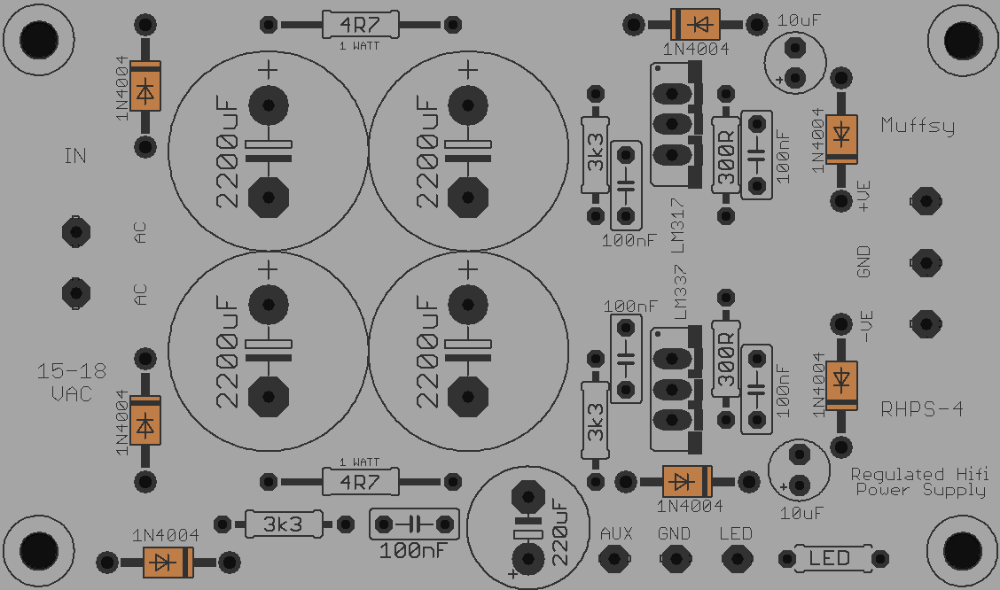
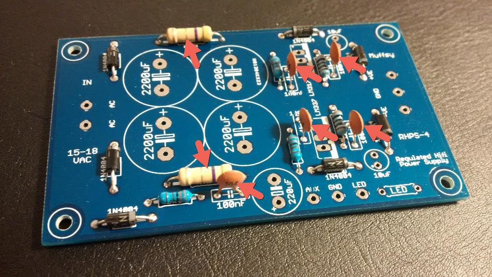
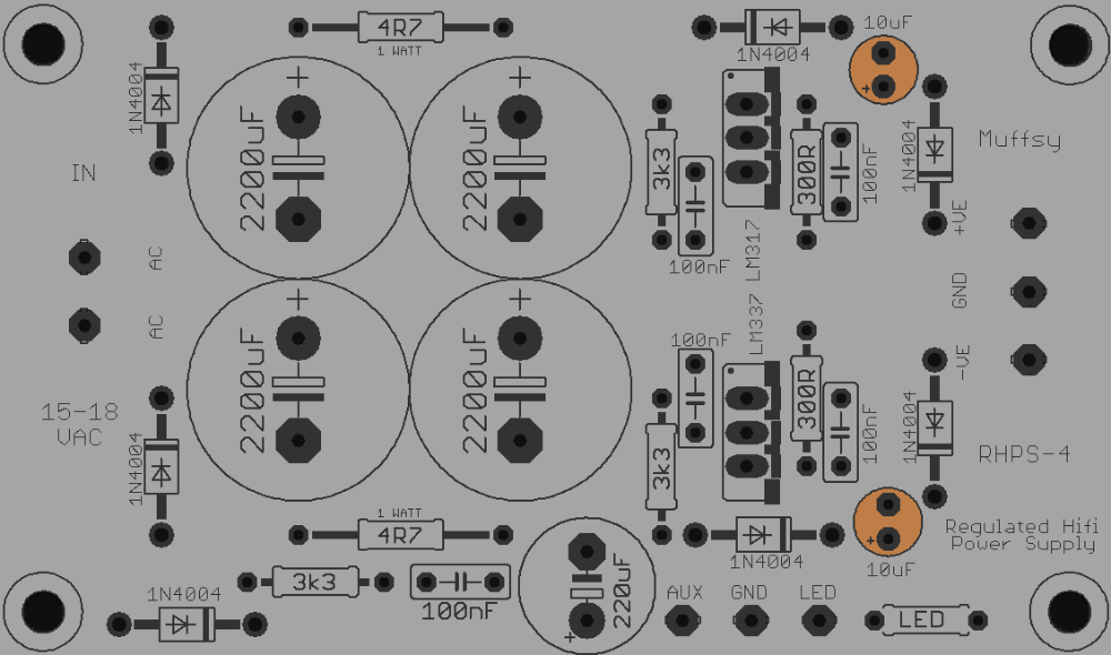
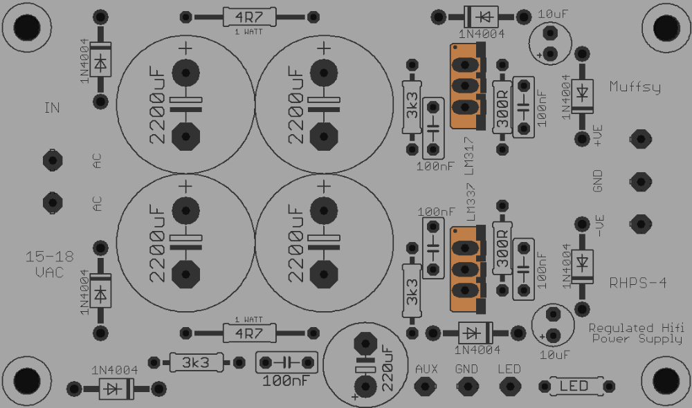
The picture below is a larger version of your printed circuit board. For each step, this will be used to show you which components you will be adding to the board.
.png)
This picture shows you where you are in the build process. It also shows what each component looks like, and it will contain special instructions or information.
These are the components needed to build the power supply.
There are lots of options available, alternatives from Mouser and Farnell are given where applicable:
| Quantity | Component | Mouser Alternatives | Farnell Alternatives |
|---|---|---|---|
| 7 | Diodes, 1N4004 | 583-1N4004-T | 12T2303 |
| 2 | Resistors, 0.25W Metal Film, 300 ohm | 603-MFR-25FRF52-300R | 38K5327 |
| 3 | Resistors, 0.25W Metal Film, 3300 ohm | 603-MFR-25FRF52-3K3 | 38K5334 |
| 2 | Resistors, 1W, 4.7 ohm | 660-SPR1CT52R4R7J | 59T0018 |
| 5 | Ceramic Capacitors, 100 nF | 140-50V5-104Z-RC | 97K4396 |
| 2 | Electrolytic Capacitors, 25V or higher, 10 uF | 647-UVR1H100MDD1TD | 33K2335 |
| 1 | Electrolytic Capacitor 35V or higher, 220 uF (Grid: 5.8 mm, Diameter: 10 mm) | 647-UVR1H221MPD1TD | 09J5056 |
| 4 | Electrolytic Capacitors, 50V, 2200 uF (Grid: 7.5 mm, Diameter: 16 mm) | 647-UVK1H222MHD | 55K2543 |
| 1 | Voltage Regulator, LM317T | 511-LM317T | 58K8936 |
| 1 | Voltage Regulator, LM337T | 512-LM337T | 58K8937 |
| 1 | Wall Adapter, 15-18V AC | Suitable wall adapters | Suitable wall adapters |
| 1 | Male Power Jack, 2.1 mm | According to project requirements *) | According to project requirements *) |
| 1 | Screw Terminal, DG301, 2 Positions (Grid: 5 mm) | 710-691102710002 | 04R6852 |
| 1 | Screw Terminal, DG301, 3 Positions (Grid: 5 mm) | 710-691102710003 | 04R6853 |
*) It's hard to give a good suggestion of a power jack, as this will depend on your requirements. Please note that a power jack is included with the Muffsy Back Panel.
Before you move on, you might want to have a look at how to modify the Muffsy Hifi Dual Power Supply and its AUX Power, so you can get the component values you need.
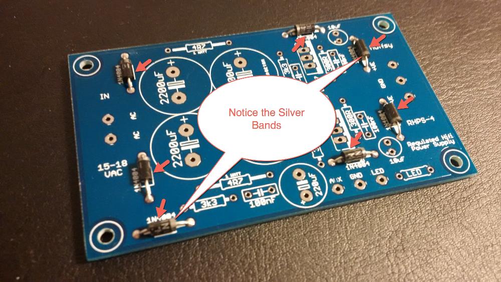
Step 1: Solder the Diodes
There are seven 1N4004 diodes on the board. They have to be oriented correctly. The silver band on each diode matches the symbol on the printed circuit board.
.jpg)
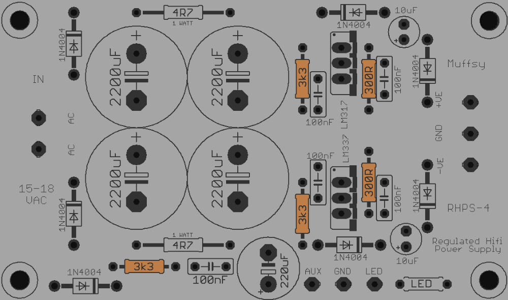
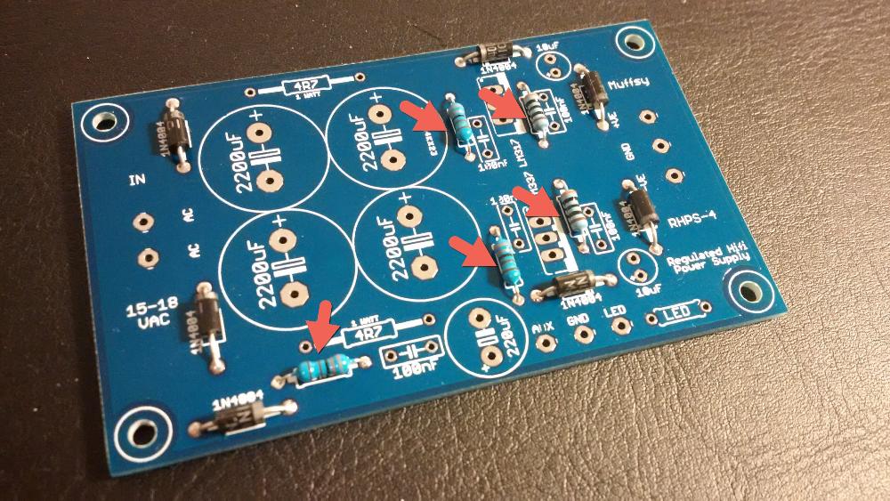
Step 2: Solder the 0.25W Resistors
There are five of the 0.25W resistors, they can be oriented whichever way you want. It is a good idea to measure them before they are soldered in place.
If you need the exact same positive and negative output voltage, you should match the four resistors on the right side of the board. If you don't, the voltages will only differ by 20-30 mV maximum.
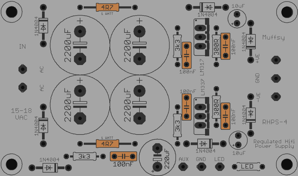
Step 3: Solder 1W Resistors and Ceramic Capacitors
The two 1W resistors and the five ceramic capacitors can be mounted either way. I like to mount the capacitors so the text can be seen.
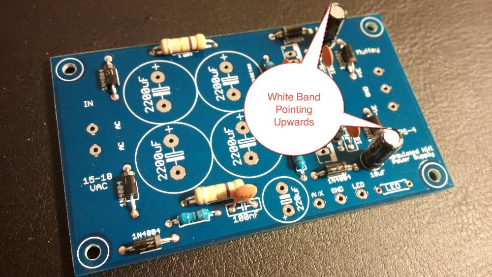
Step 4: Solder 10 uF Electrolytic Capacitors
There are two of these small electrolytic capacitors. Make sure that the white band (negative) is pointing upwards when the board is oriented as on the pictures.
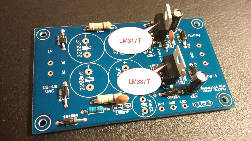
Step 5: Solder the Voltage Regulators
There are two voltage regulators. One positive and one negative. The positive is the uppermost one on the pictures, the negative is the lower one.
Make sure that the regulators are mounted the right way. The metal "backside" must point to the right, when the board is oriented as on the pictures below. If they are placed wrong, the power supply will not work at all.
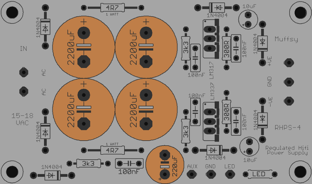
Step 6: Solder the 220 uF and 2200 uF Capacitors
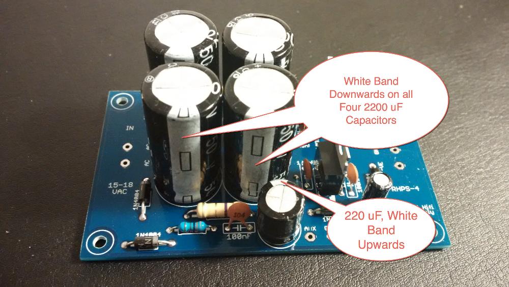
The smaller 220 uF capacitor must be oriented with the white band pointing upwards. If you have decided to improve the voltage ripple, substitute this capacitor with the new one.
The four larger 2200 uF capacitors must have the white band pointing downwards.
Step 7: Solder Screw Terminals
The last components to go on the board are the two screw terminals.
The screw terminal with two connections is for the 15-18V AC input, from the wall adapter. The screw terminal with three holes is for the +/- 15V DC output and ground.
Orientation of the Screw Terminals
B0905 Cabinet: If you are using a B0905 cabinet, you really want the holes of the screw terminals pointing inwards. If you don't, you risk shorting the power cables against the wall of the cabinet.
If you have a lot of space in your cabinet, having the holes of the screw terminals pointing outwards from the board is normally the way to go.
Construction Complete
Congratulations, you have built a power supply.
To complete your build, continue to the following instructions: