Build the Muffsy Hifi Dual Power Supply v3
Here are the build instructions for the Muffsy Hifi Dual Power Supply v3.
A 15-18 volts AC wall adapter (do not exceed 18 volts) is needed to make this power supply work. Here is some more information about what you need to build the Muffsy Phono Preamp and Power supply.
You can also have a look at the schematics for the Muffsy products under the Modify It page.
Illustrations Explained
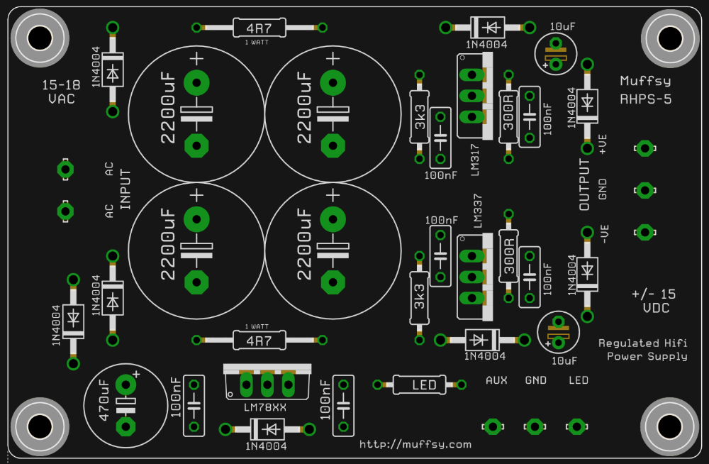
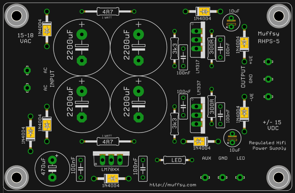
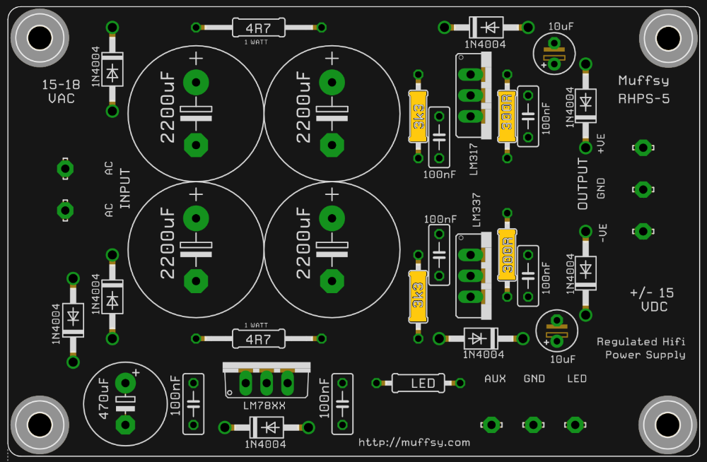
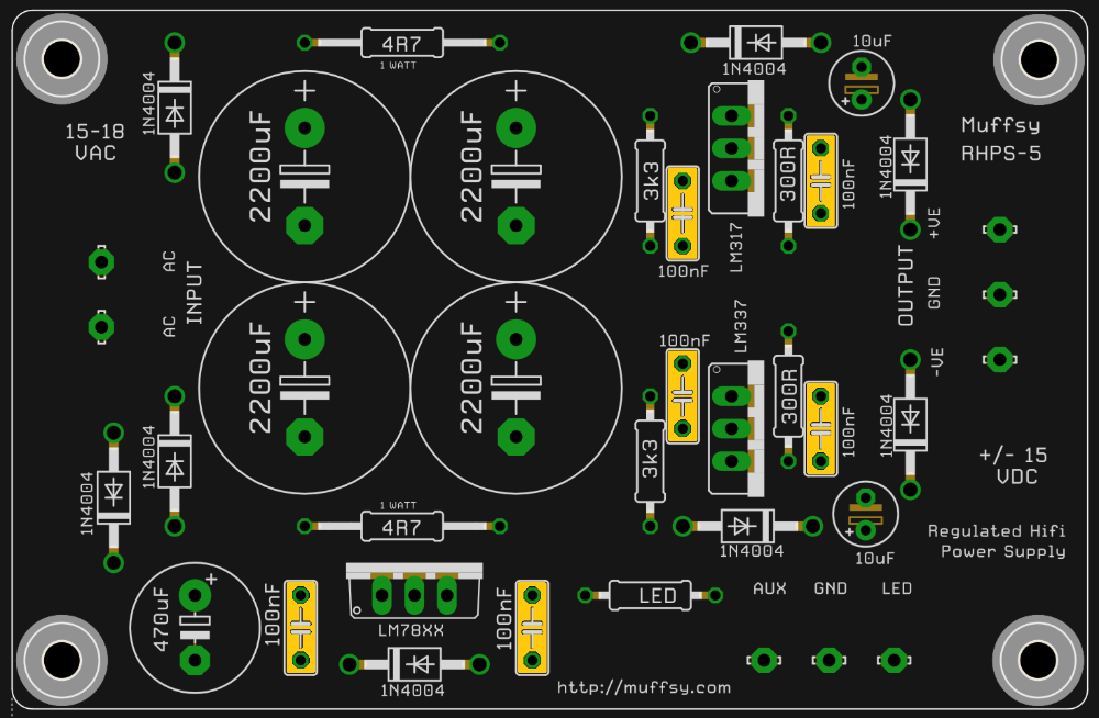
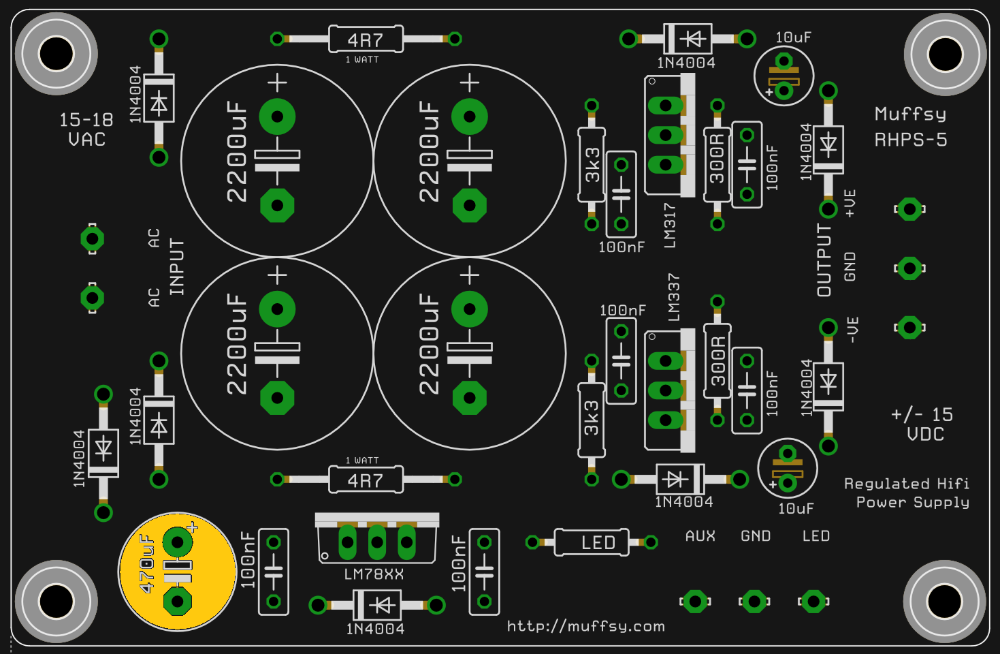
The picture below is a larger version of your printed circuit board. For each step, this will be used to show you which components you will be adding to the board.
This picture shows you where you are in the build process. It also shows what each component looks like, and it will contain special instructions or information.
These are the components needed to build the power supply.
| Quantity | Component |
|---|---|
| 8 | Diodes, 1N4004 |
| 2 | Resistors, 0.25W Metal Film, 300 ohm |
| 2 | Resistors, 0.25W Metal Film, 3300 ohm |
| 2 | Resistors, 1W, 4.7 ohm |
| 6 | Ceramic Capacitors, 100 nF |
| 2 | Electrolytic Capacitors, 25V or higher, 10 uF |
| 1 | Electrolytic Capacitor 35V or higher, 470uF (Grid: 5.8 mm, Diameter: 10 mm) |
| 4 | Electrolytic Capacitors, 35V or higher, 2200 uF (Grid: 7.5 mm, Diameter: 16 mm) |
| 1 | Voltage Regulator, LM317T |
| 1 | Voltage Regulator, LM337T |
| 1 | Voltage Regulator, LM7815 |
| 1 | Wall Adapter, 15-18V AC |
| 1 | Screw Terminal, DG301, 2 Positions (Grid: 5 mm) |
| 1 | Screw Terminal, DG301, 3 Positions (Grid: 5 mm) |
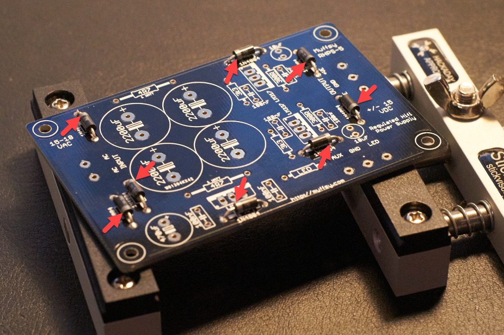
Step 1: Solder the Diodes
There are eight 1N4004 diodes on the board. Take your time and make sure you have them oriented correctly. The silver band on each diode matches the symbol on the printed circuit board.
Step 2: Solder the 0.25W Resistors
Before you continue, consider if you want to change the output voltage. The Muffsy kits are made for +/-15V (which is what you get if you use the included components), but you may have other plans for the power supply. If you plan to use other operational amplifiers, check what their maximum voltage is. Some may need less voltage.
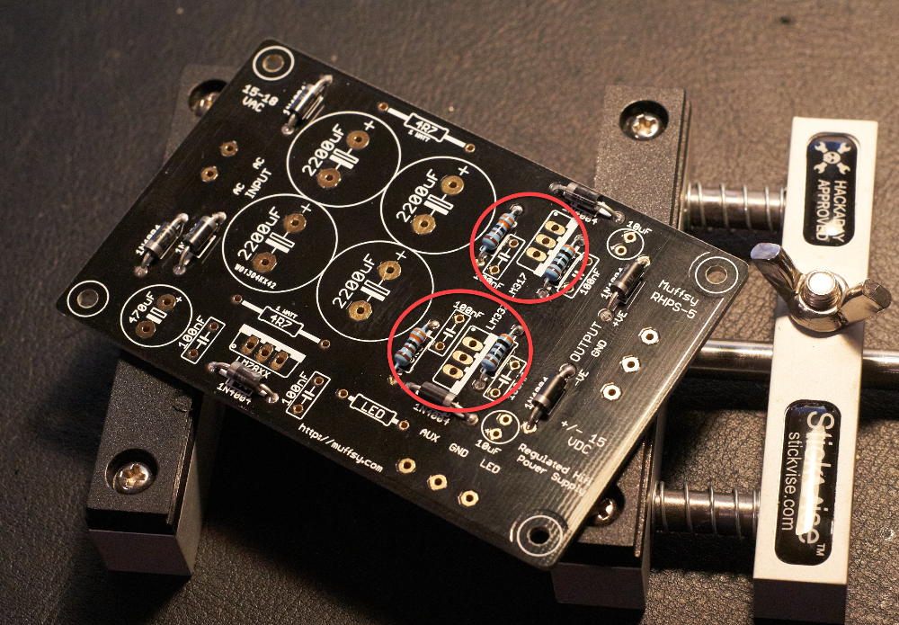
There are four of the 0.25W resistors, they can be oriented whichever way you want. It is a good idea to measure them before they are soldered in place.
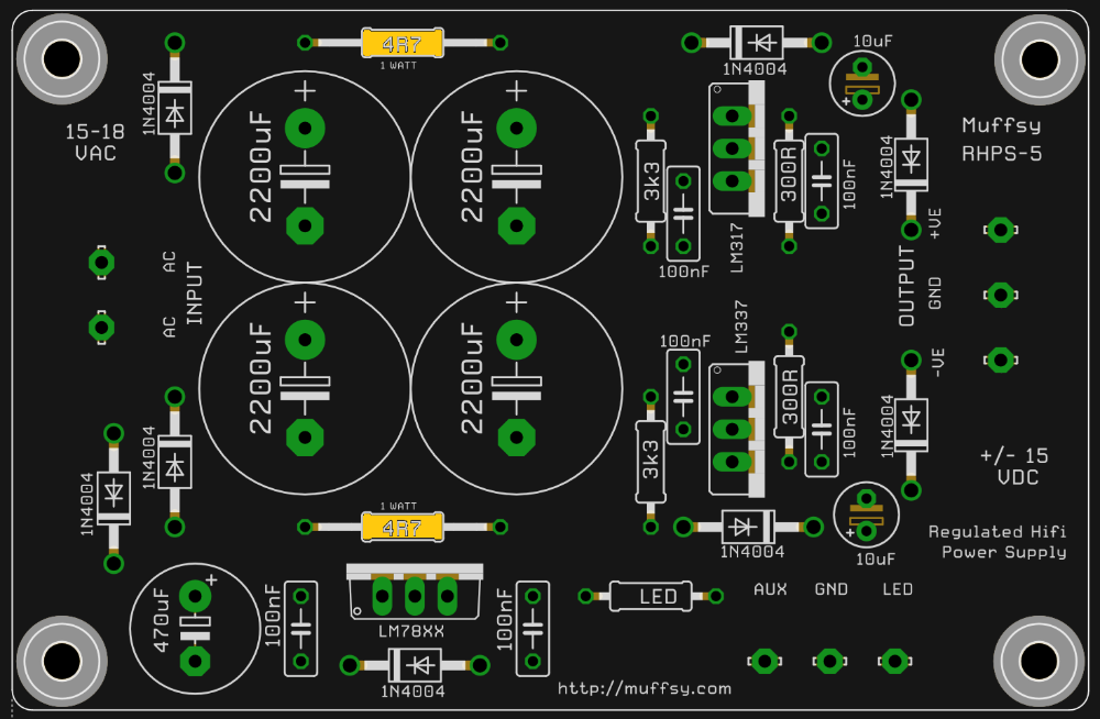
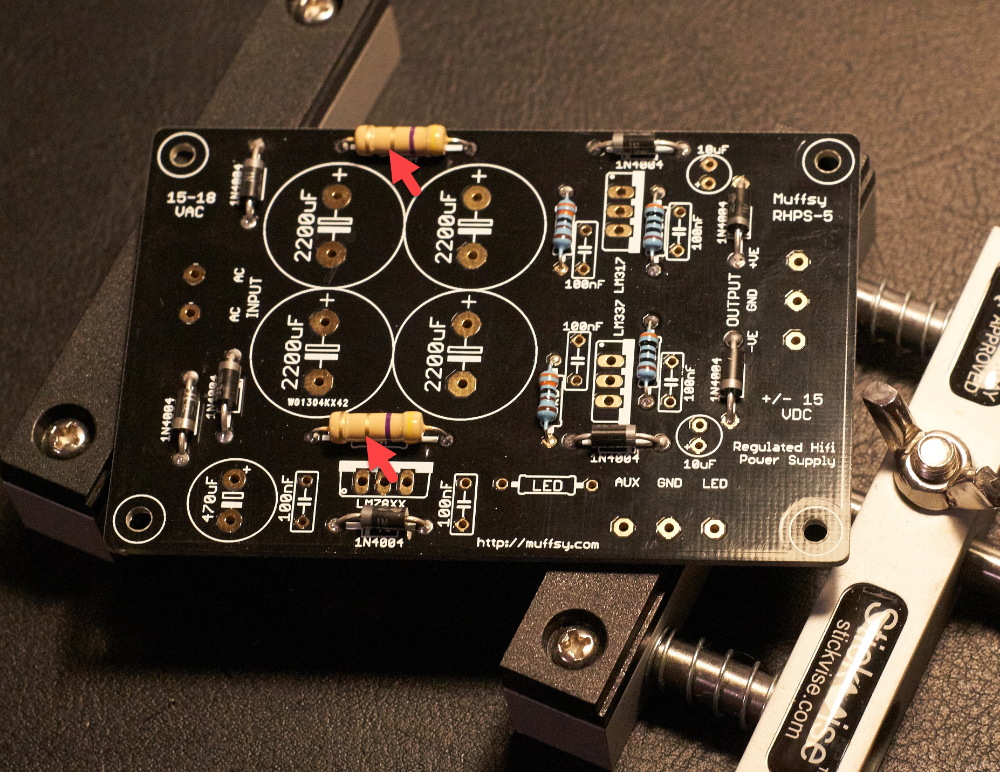
Step 3: Solder 1W Resistors
The two 1W resistors can be mounted either way.
Step 4: Solder the Ceramic Capacitors
Next you've got six ceramic capacitors to place on the board. The orientation does not matter for these, but I like to place them so that the text is outwards and visible.
.png)
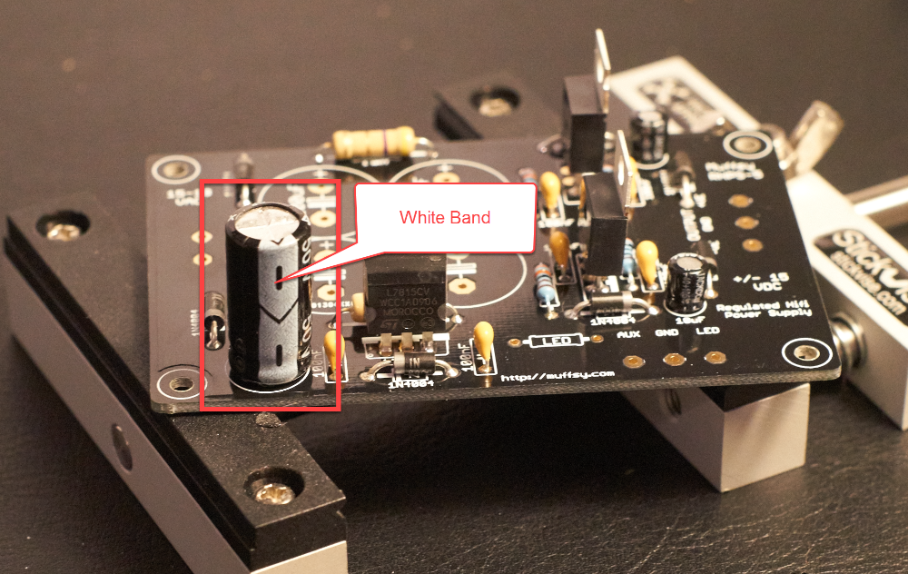
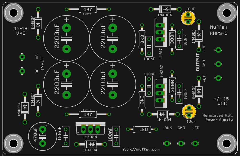
Step 5: Solder the 10 uF Electrolytic Capacitors
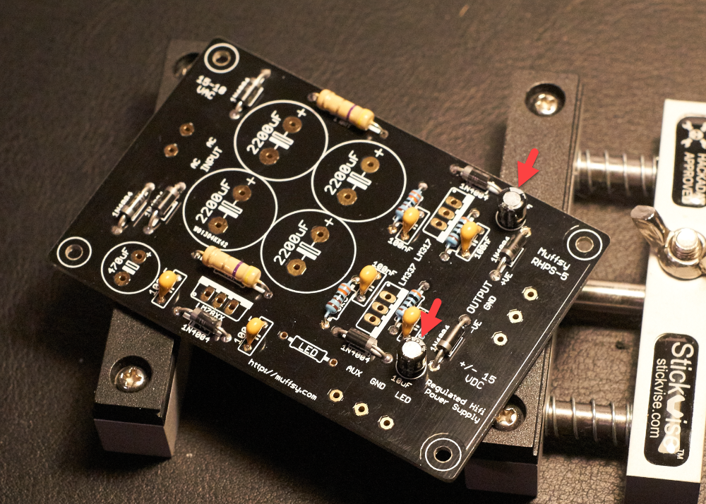
These two capacitors must be mounted the right way around. The white band (the negative side of the capacitors) are pointed upwards on the board. See the pictures below for reference.
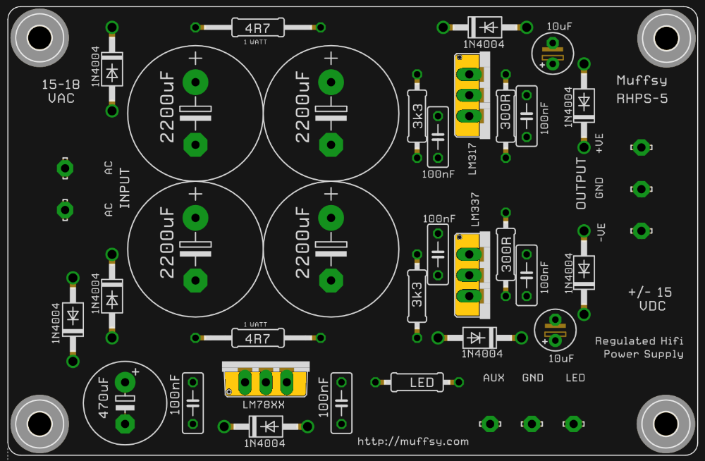
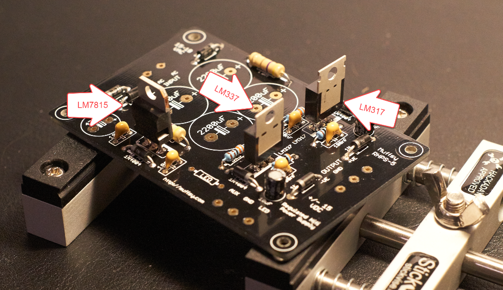
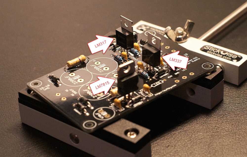
Step 6: Solder the Voltage Regulators
The board has three voltage regulators. One for +15V, one for -15V and a third one for +15V AUX power. They are three different models, make sure you identify them as LM317, LM337 and LM7815.
It's important to get both the placement and the orientation of the voltage regulators correct, so there's two pictures from different angles.
Step 7: Solder the 470 uF Electrolytic Capacitor
The orientation of this capacitor is important, place it as on the pictures below and solder it in place.
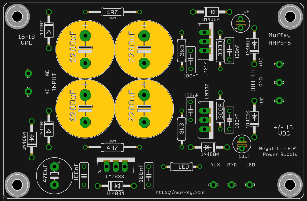
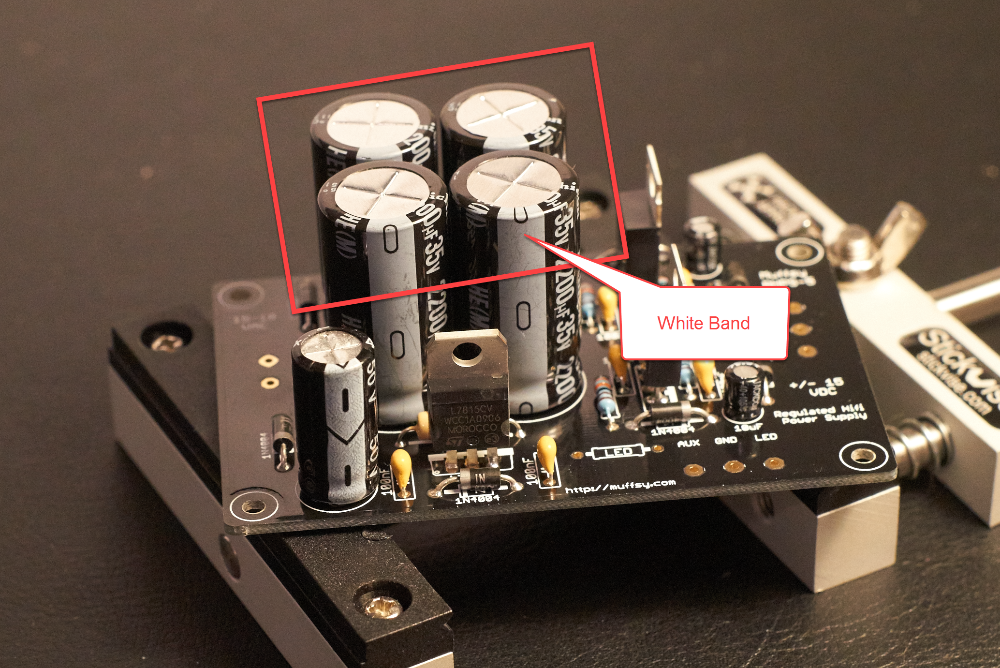
Step 8: Solder the 2200 uF Electrolytic Capacitors
There are four large 2200 uF electrolytic capacitors on the board, for smoothing the rectified AC voltage.
Orientation is important, all the white bands are facing downwards. Double check the orientation before you solder these capacitors in place, they can be pretty hard to desolder.
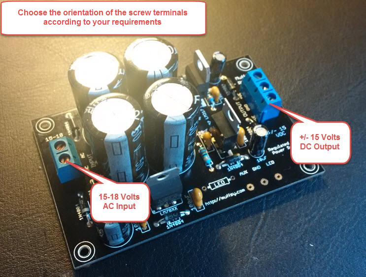
Step 9: Solder Screw Terminals
If you are building your Muffsy Phono Preamp or MC Head amp into a B0905 enclosure, please don't solder the screw terminals just yet.
The construction pages for the Phono Preamp and MC Head Amp contain info on how to mount these terminals:
If you are using a custom enclosure for your build, the screw terminals may be soldered in place now. You still might want to consider fitting the cables before soldering the terminals to the PCB. Tinning the cable ends might also make it easier to insert them into the screw terminals.
The screw terminal with two connections is for the 15-18V AC input, from the wall adapter. The screw terminal with three holes is for the +/- 15V DC output and ground.
Construction Complete
Congratulations, you have built a power supply.
To complete your build, continue to the following instructions: