Build the Muffsy Phono Preamp PP-4
This kit is for sale for on Tindie:
The Muffsy Phono Preamp kit comes with all on-board components. Have a look at this page to learn about how to turn it into a complete and fully working phono stage.
You can also have a look at the schematics for the Muffsy products under the Modify It page.
- Here are the Muffsy Phono Preamp PP-3 Rev A instructions (the one with the black board)
Before You Begin Construction
PLEASE NOTE:
- Make sure you have time to construct the kit. If you are stressed, building the kit will not be very rewarding. And it often leads to mistakes.
- Familiarize yourself with the instructions before you start building the Muffsy Phono Preamp.
- Take the time needed to double-check component values and placements.
- Even if you're not using the Muffsy Power Supply, Back Panel or the B0905 cabinet, the information given here will serve as inspiration for your build.
- Wash your hands carefully afterwards if you're using leaded solder. Do not lick your fingers or touch any food items while working.
Illustrations Explained
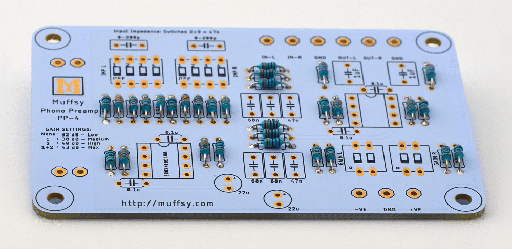
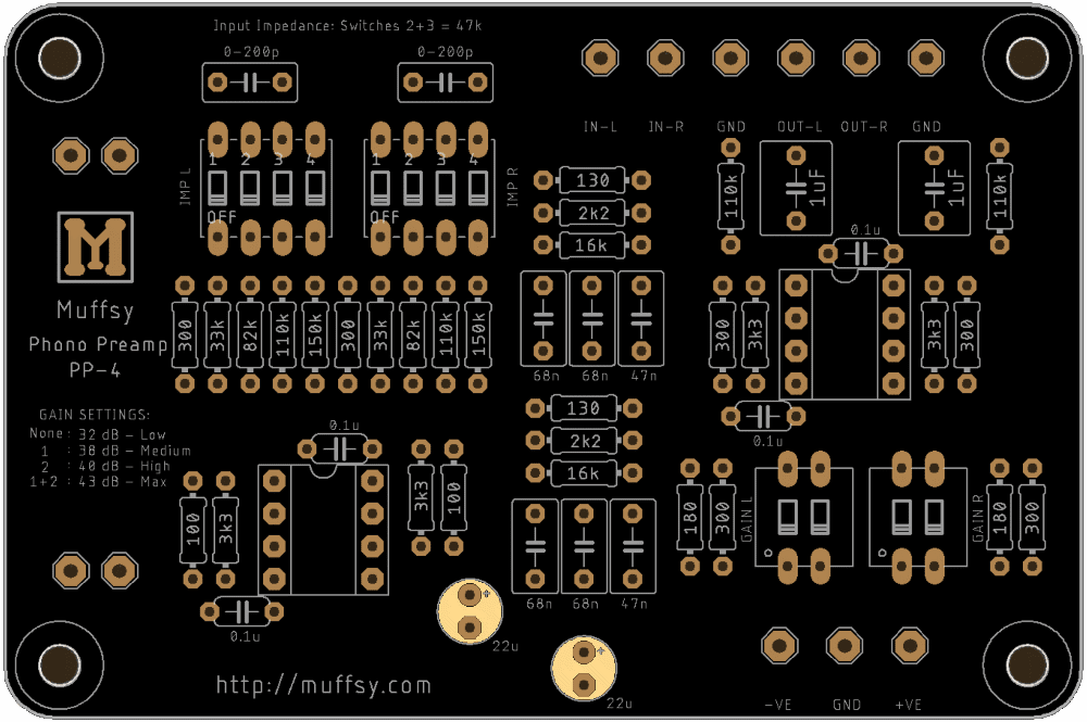
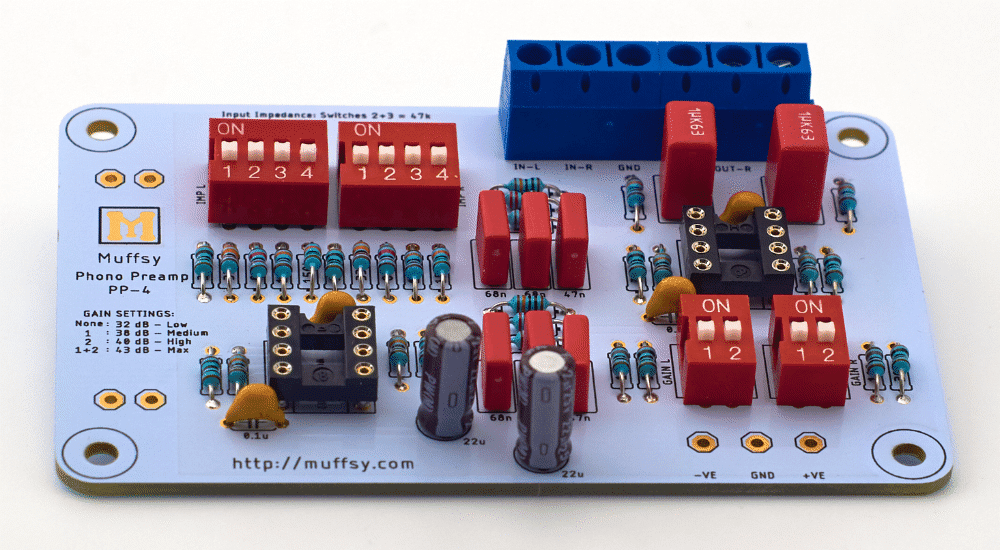
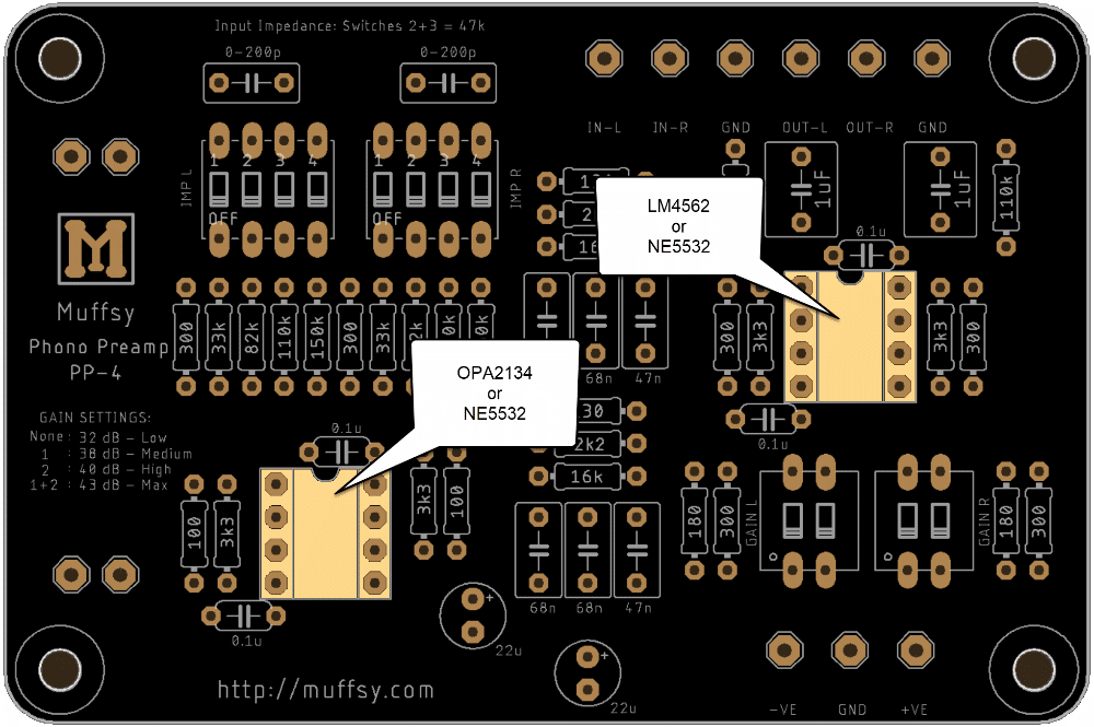
The picture below is a larger version of your printed circuit board. For each step, this will be used to highlight which components you will be adding to the board.

You will also get a live view of where you are in the build process. It will show you what each component looks like, and present special information if needed.
Step 1: Check the Kit Contents
Before you start building, check that you have all components and familiarize yourself with the kit. Here's a list of the kit's contents:
| Quantity | Component |
|---|---|
| 1 | Muffsy PP-4 Printed Circuit Board |
| 2 | Resistors 0.25W, 100 ohm |
| 2 | Resistors 0.25W, 130 ohm |
| 2 | Resistors 0.25W, 180 ohm |
| 6 | Resistors 0.25W, 300 ohm |
| 2 | Resistors 0.25W, 2k2 ohm |
| 4 | Resistors 0.25W, 3k3 ohm |
| 2 | Resistors 0.25W, 16k ohm |
| 2 | Resistors 0.25W, 33k ohm |
| 2 | Resistors 0.25W, 82k ohm |
| 4 | Resistors 0.25W, 110k ohm |
| 2 | Resistors 0.25W, 150k ohm |
| 2 | 8-Pin DIL Sockets |
| 2 | 2-Way DIP Switches |
| 2 | 4-Way DIP Switches |
| 2 | Operational Amplifiers |
| 4 | Ceramic Capacitors, 100 nF |
| 2 | Polyester Film Capacitors, 47 nF |
| 4 | Polyester Film Capacitors, 68 nF |
| 2 | Polyester Film Capacitors, 1 uF |
| 2 | Electrolytic Capacitors, 22 uF |
| 2 | DG301 Screw Terminals, Three Positions |
| 30 cm (1 ft) | RVVP 2x0.2 shielded audio cable |
All resistors are 1/4W, metal film, 1% tolerance.
Note:
This high quality printed circuit board has plated-through holes. Do not attempt to drill the holes to make them larger, doing so will destroy the board. The four mount holes, one in each corner, may be drilled to size.
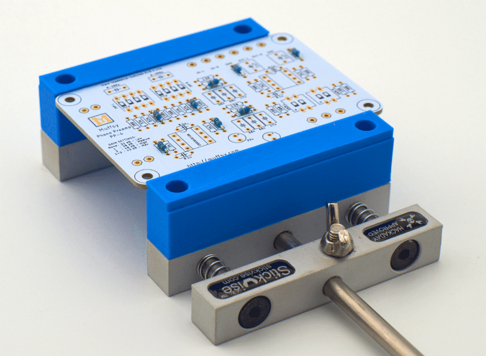
Step 2: Solder the Resistors
There is a total of 30 resistors that go onto the printed circuit board.
The resistors are bidirectional, meaning that you don't have to worry about which way they are oriented.
It's recommended that you measure the resistors before you mount them, and make absolutely sure that the right resistors go in the correct positions.
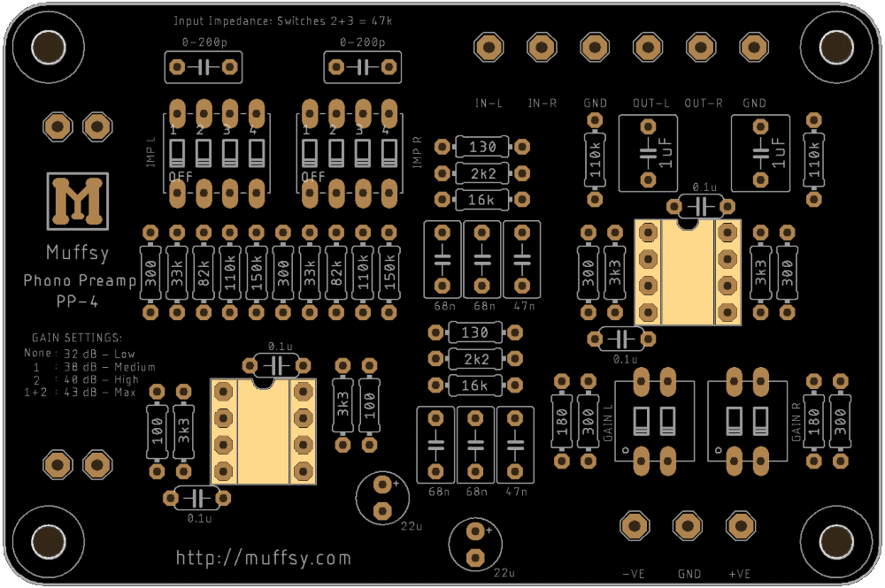
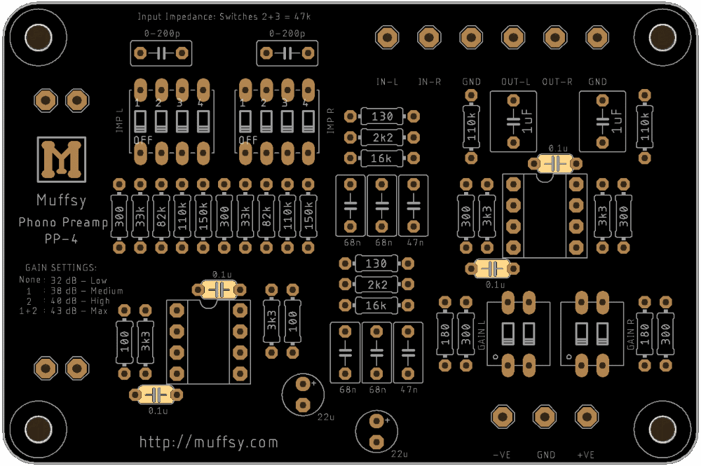
Use this high resolution picture of the PCB to verify the placement of all resistors:

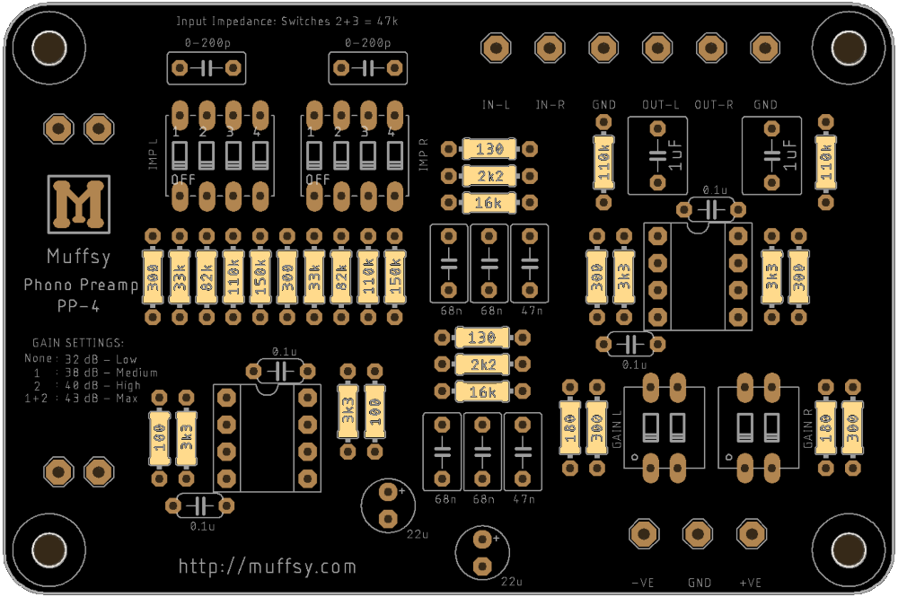
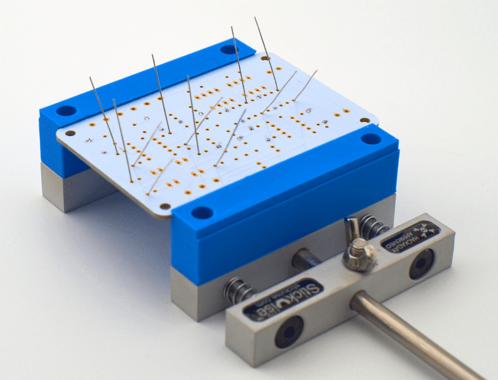
Mount just a few resistors at the time. It will be a lot easier to solder them, and there's less chance of confusion. Check and double-check the values before soldering the resistors in place and snip the resistor leads as you go.
The picture below shows all the resistors soldered in place. The resistors in the kit all have 1% tolerance and a temperature coefficient of ±50ppm/°C.
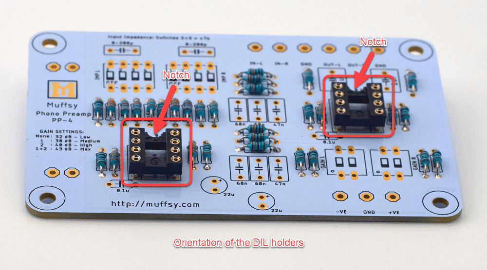
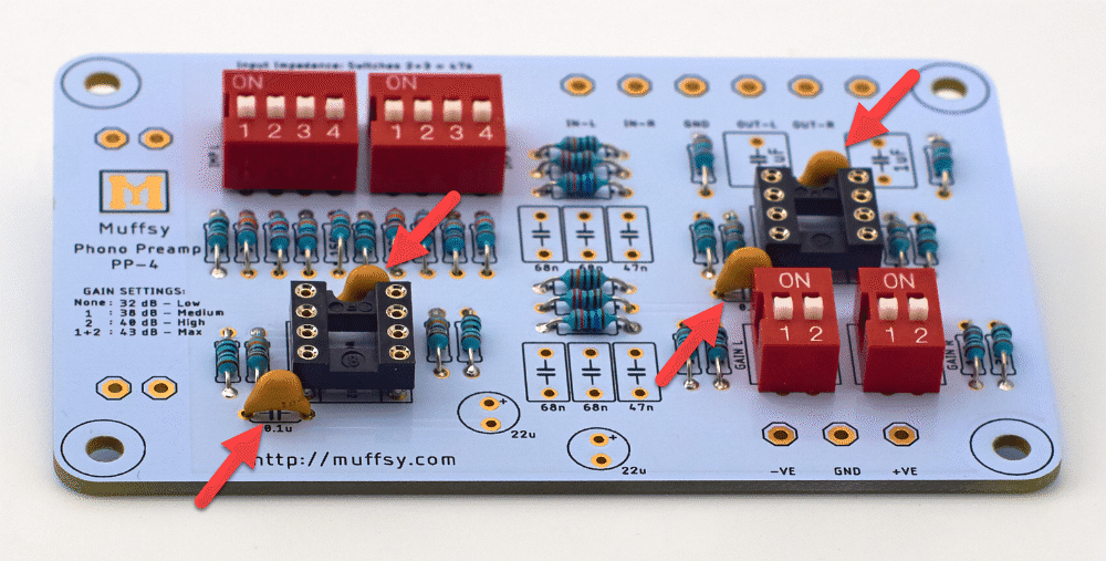
Step 3: Solder the DIL Sockets
These are the sockets for the operational amplifiers. They will make it easier to replace the small chips later on if you should want to. Soldering the sockets will also make sure you don't overheat the operational amplifiers when installing them.
The orientation is very important for these two sockets, get it wrong and you will be confused about which way to mount the operational amplifiers. There's a notch in the socket that matches up with the picture on the printed circuit board, as shown in the pictures below.
Using a piece of masking tape to hold the sockets in place might be a good idea.
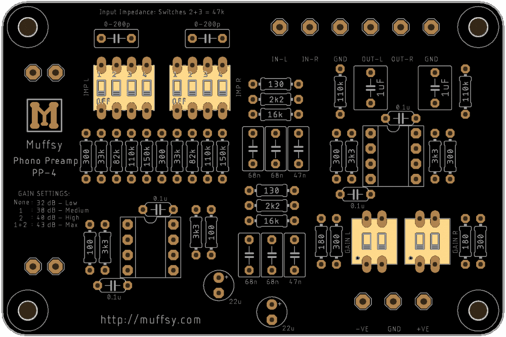
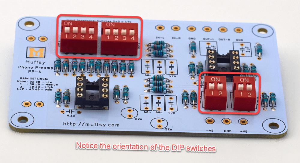
Step 4: Solder the DIP-Switches
These four DIP-switches are here to adjust the input impedance and overall gain of the phono stage.
It is absolutely essential that you get the orientation right. If you don't, adjusting the features of the preamp will be very difficult and confusing.
Use a piece of masking tape to hold the switches in place while you solder.
Step 5: Solder the Ceramic Capacitors
There are four ceramic capacitors on the board, surrounding the op amp sockets. You don't have to worry about the orientation of these capacitors, I like to place them so that the text is showing.
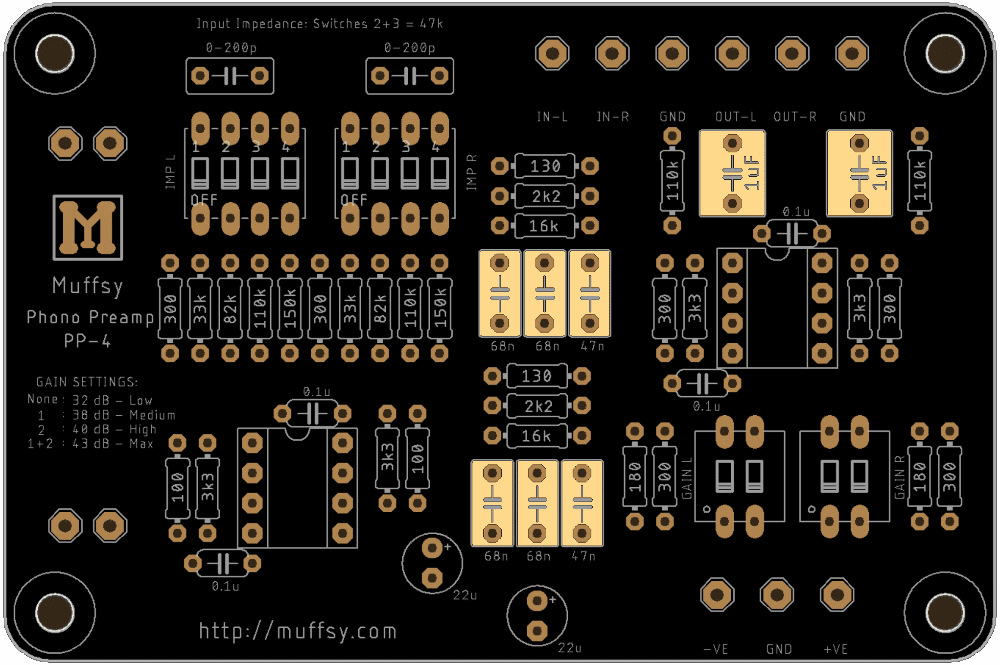
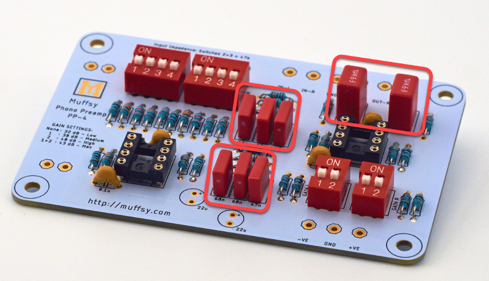
Step 6: Solder the Wima Film Capacitors
There are eight Wima MKS2 capacitors in all.
Start with the six capacitors in the RIAA equalization filter before you continue to the two output capacitors. They are bipolar, so orientation is not significant. I still like to place them so that the text is visible.
Make sure that the right value capacitor is mounted in the right spot. The four 68 nF and the two 47 nF capacitors are very similar in size.
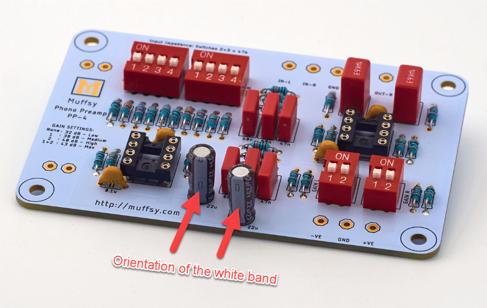
Step 7: Solder the Electrolytic Capacitors
The two 22 uF electrolytic capacitors must be oriented correctly, or there's a chance they will go up in smoke.
The board shows a plus (+) symbol, this is where the longer leg of the capacitors will go. The capacitors have a white band with several minus signs (-), this side has the shorter leg. This minus side goes downward when the board is oriented as shown on the pictures.
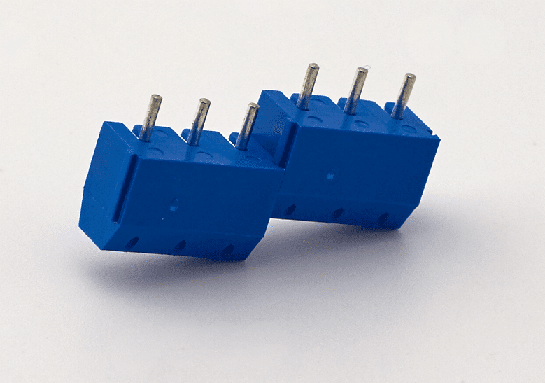
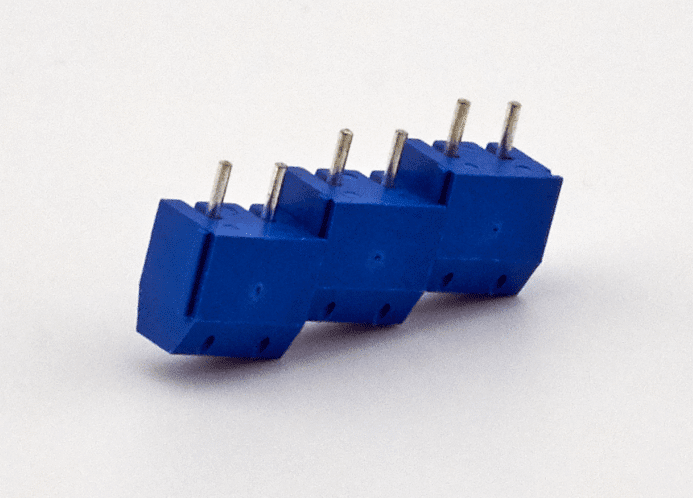
Step 9: Solder the Screw Terminals
There are two screw terminals with three positions, or three screw terminals with two positions included in the kit. These are for the audio inputs and outputs.
Join the screw terminals together as shown below to make a screw terminal with six positions:
Solder the screw terminals to the board, with the holes facing outwards:
Step 9: Optional - Solder the Input Capacitors
For some very special setups/cartridges, you may need some additional input capacitance. If you do, mount these two capacitors now.
It is very likely that you won't need them, and they are not included in the kit.
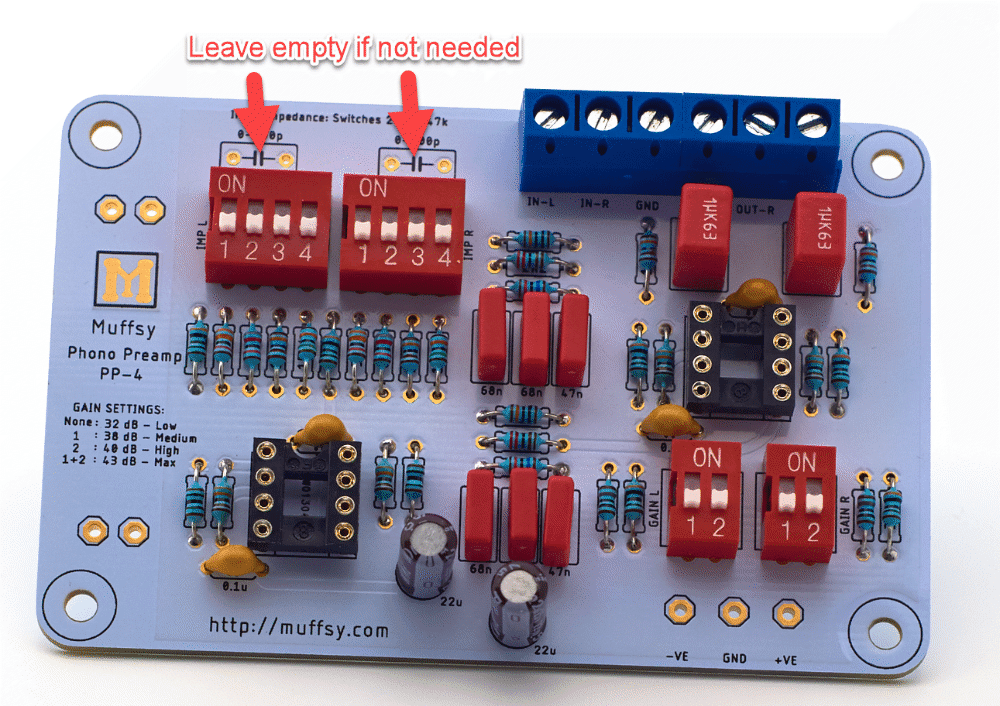
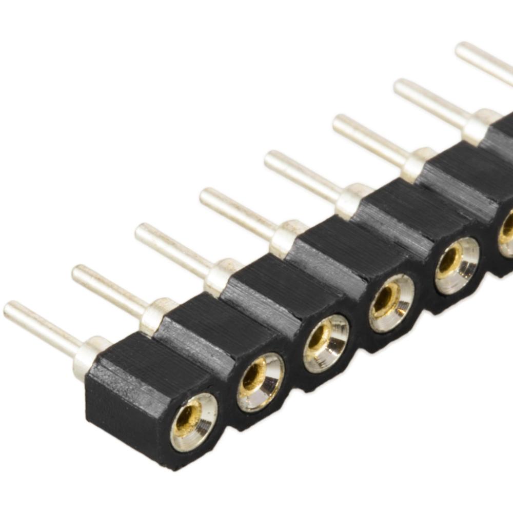
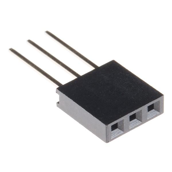
To ease the installation of the input capacitors, use stackable pin headers. Either round ones that you can break off, or square ones where you can cut off the middle pin.
Film capacitors with 5 mm / 5.08 mm pin spacing are suitable.
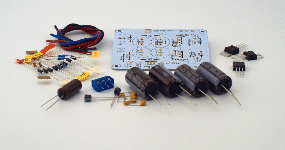
Step 10: Build the Power Supply
Follow the build instructions for the Muffsy Power Supply v4.
PLEASE NOTE: Make sure that you don't exceed the maximum voltage of your operational amplifiers. The Muffsy Power Supply delivers +/- 15 volts, which is fine for the op amps delivered with the kit. Others, like certain discrete operational amplifiers, max out at +/-12 volts. (Have a look here if you need to change the Muffsy Power Supply's voltage.)
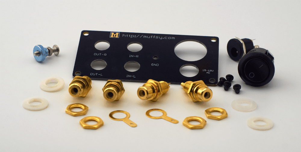
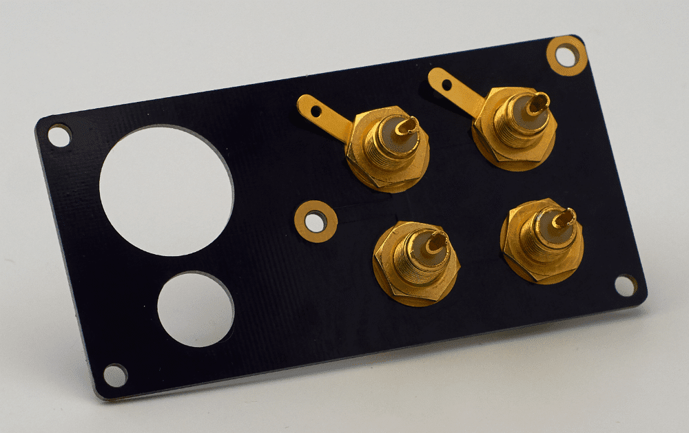
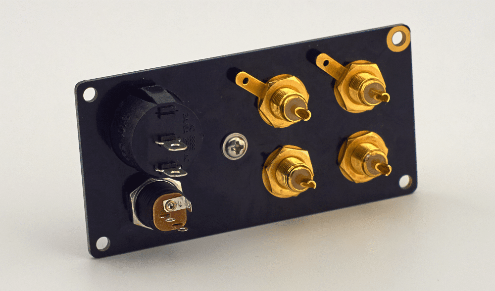
These are all the parts you'll need for the back panel, all of them are included in the back panel kit:
Take the four RCA connectors and put the plastic shims on them. The plastic shims on the front can be left out, but you will find that the connectors are easier to tighten with the shims though.
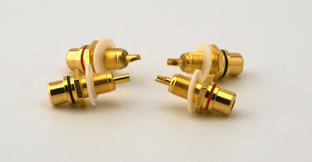
Mount the two RED connectors in the top holes, and the two BLACK connectors in the bottom holes:
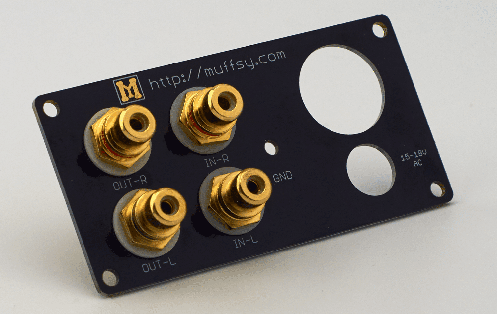
Insert the ground pads on the top two connectors and fasten them with a nut. Fasten the bottom connectors with nuts only.
It's a good idea to use a couple of wrenches to make sure the RCA connectors are tightly fastened. If they are loosened and twisted around, you could snap or short the signal cables connected on the back of the connectors.
PLEASE NOTE:
These connectors are electrically connected together inside the back panel, do not use the plastic shims on the back. If you do add these shims, you will get humming and poor sound quality.
Mount the ground screw and fasten it with a nut. Add the shim and the knurled thumb nut:
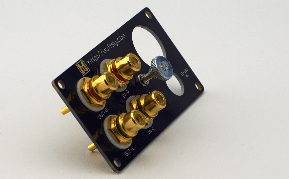
Mount the power connector. The hole is not centered, make sure it is towards the top of the board. Fasten the power connector with the nut that comes with it:
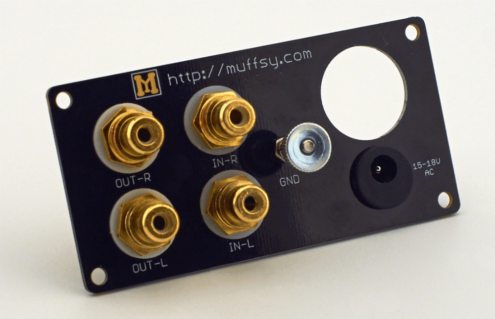
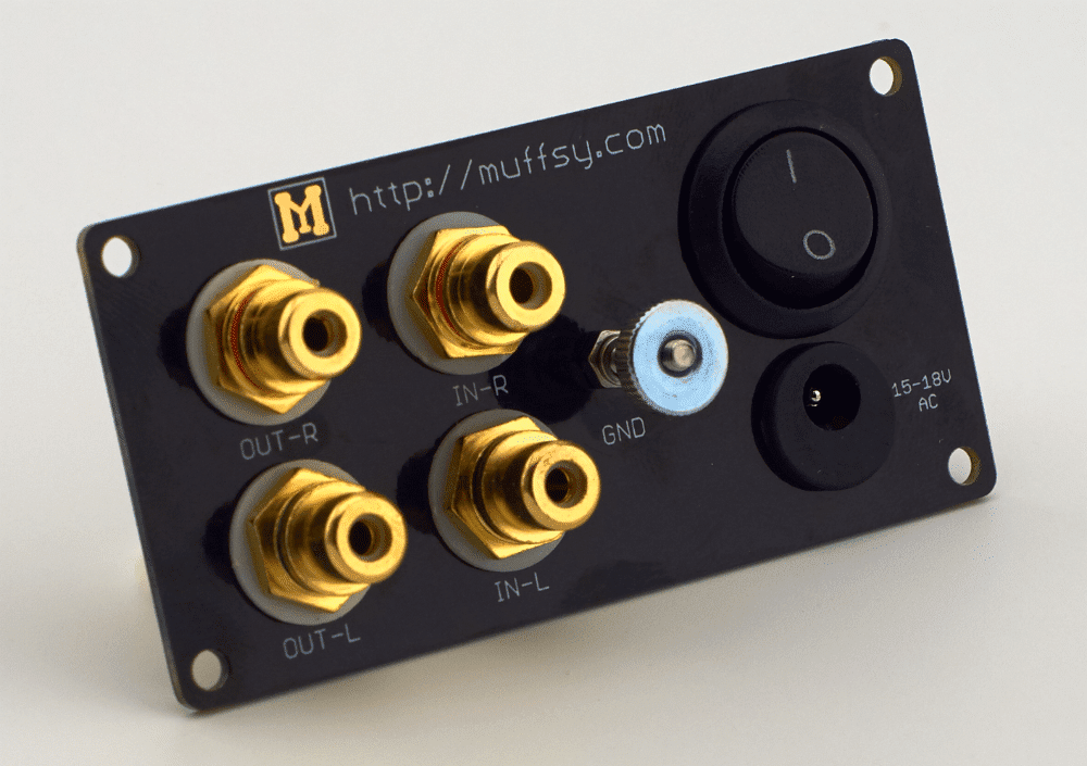
Click the power button in place. Make sure the "1" is on top:
Your back panel is now done. Here's how the backside looks when it's finished:
The information below is for the Muffsy Phono Preamp, Muffsy Power Supply and Muffsy Back Panel mounted in a B0905 cabinet.
You may want to do this in an entirely different way if you don't have all these components, if you want to incorporate the Muffsy MC Head Amp, or if you want to use a different enclosure.
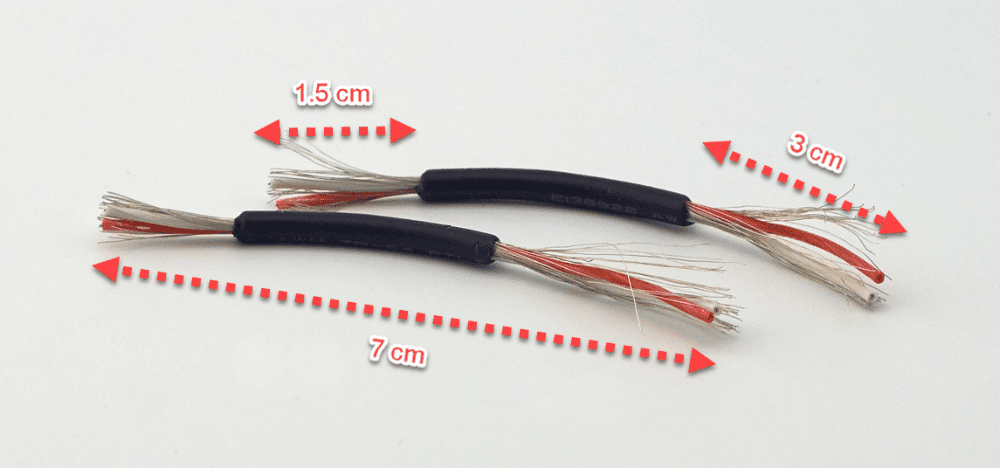
Cut two pieces of the shielded audio cable, approx 7 cm long. Strip the wires as described below:
- 3 cm at one end (this end connects to the back panel)
- 1.5 cm at the other end (this end connects to the phono preamp's in- and outputs)
When you're done, the cables will look like this:
Twist the shielding (the exposed outer wire) and strip about 0.5 cm from each of the red and white wires. It helps you later on if you tin the ends of the shorter side of the cable (that go into the in- and outputs of the phono preamp):
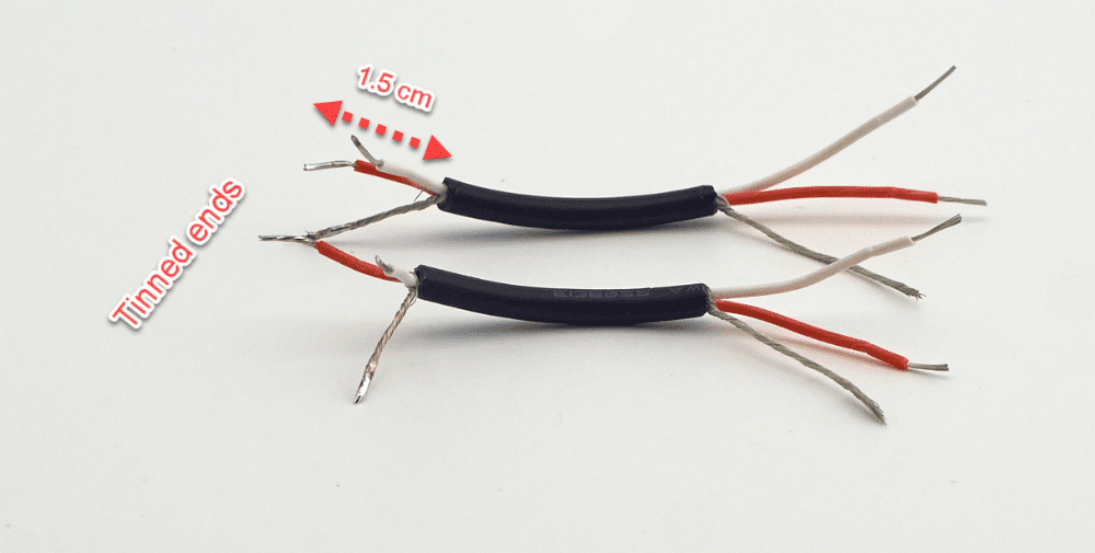
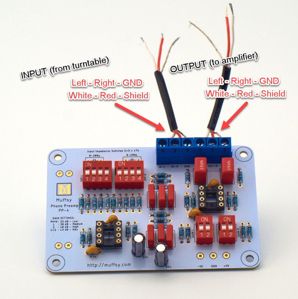
Screw the tinned 1.5 cm ends into the inputs/outputs on the Muffsy Phono Preamp board. Tinning the ends makes it much easier to insert the cables, and they will be even more securely fastened.
- IN-L / OUT-L: White
- IN-R / OUT R: Red
- GND / GND: Shield
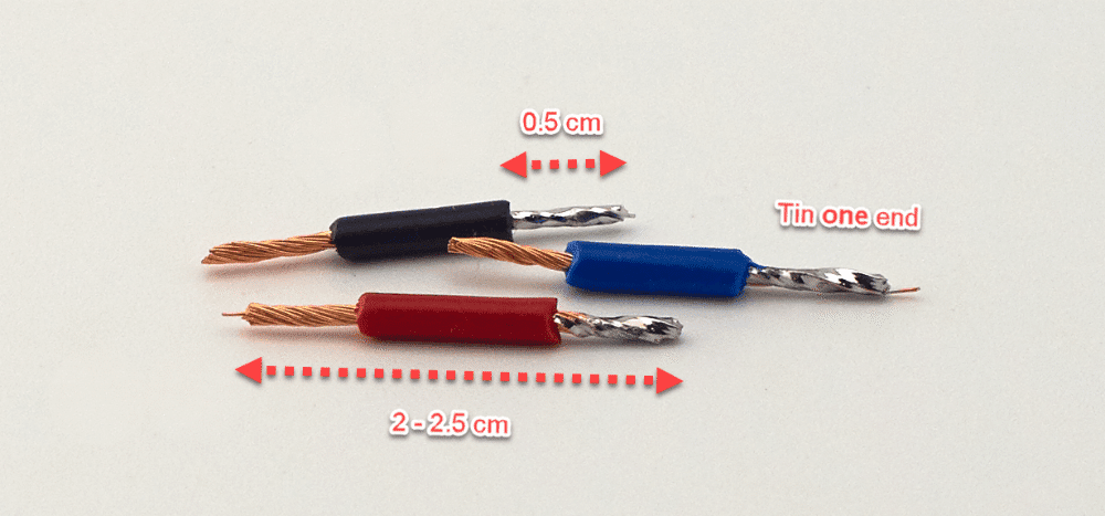
Cut three pieces of wire, red, black and blue to about 2 - 2.5 cm, and strip about 0.5 cm on each end. Tin one end of each cable:
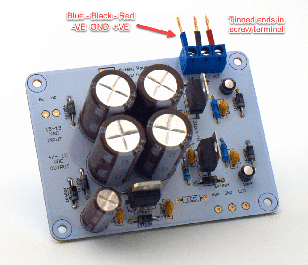
Connect the tinned end of these three wires to the power output screw terminal on the Muffsy Power Supply.
- Blue cable goes in the left hole (-VE)
- Black cable goes in the middle hole (GND)
- Red cable goes in the right hole (+VE)
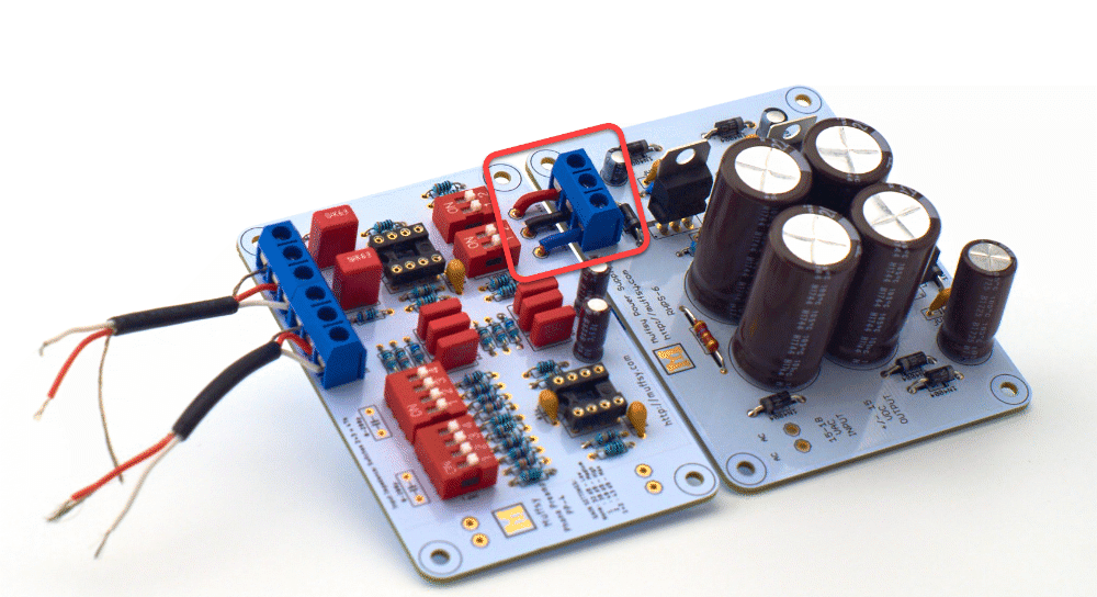
Stick the other end of these three power cables into the Phono Preamp board. It's easier to do this at an angle when you're soldering the cables in place:
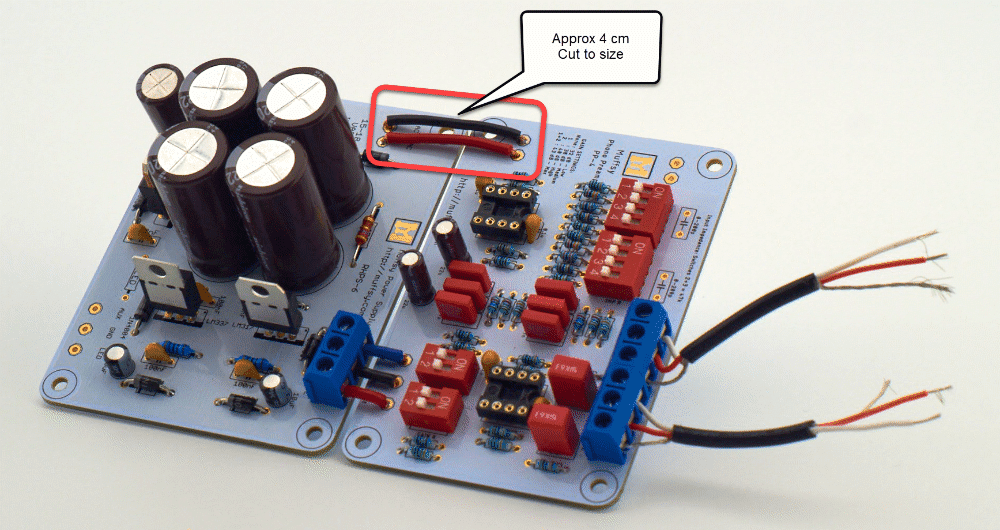
Cut a red and a black piece of wire to size, approx. 4 cm, and connect the two boards as shown below. It does not matter which color goes where.
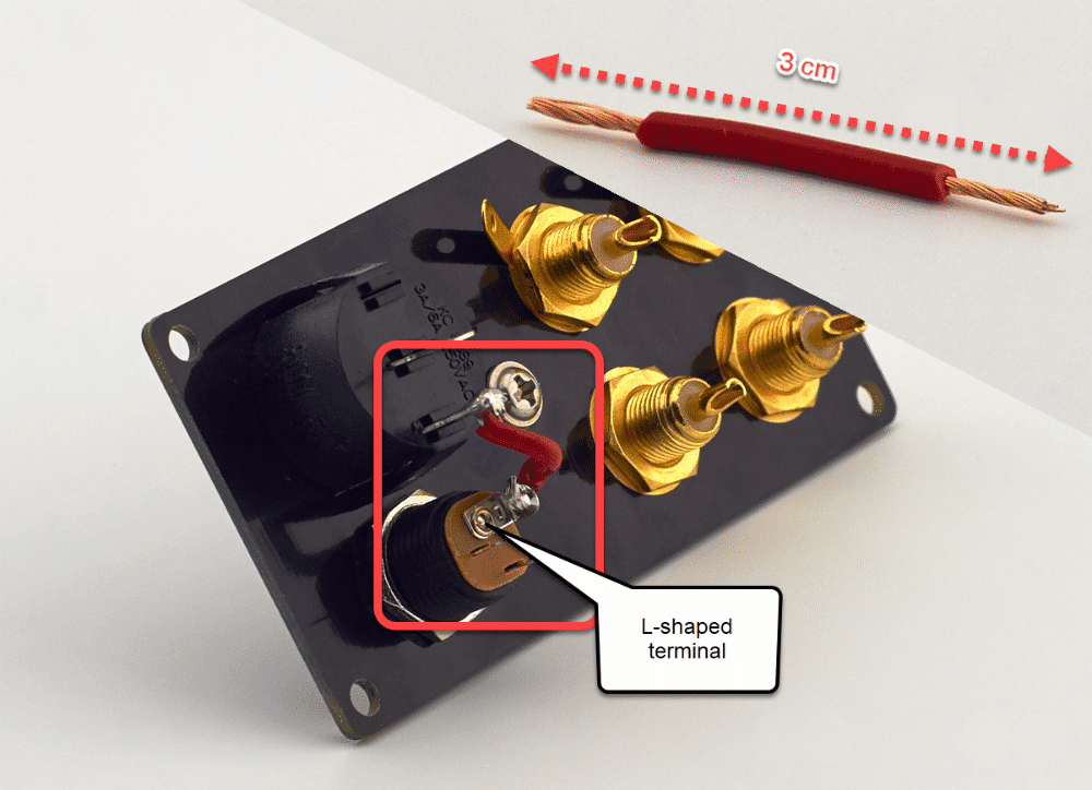
Cut a piece of red wire, ~3 cm, and strip 0.5 cm from each end.
Solder this wire between the bottom of the back panel's power button and the L-shaped terminal on the power connector.
PLEASE NOTE: Take care not to apply too much heat to the connectors on the power button. The plastic could melt otherwise. (I've used 330 degrees C / 625 degrees F).
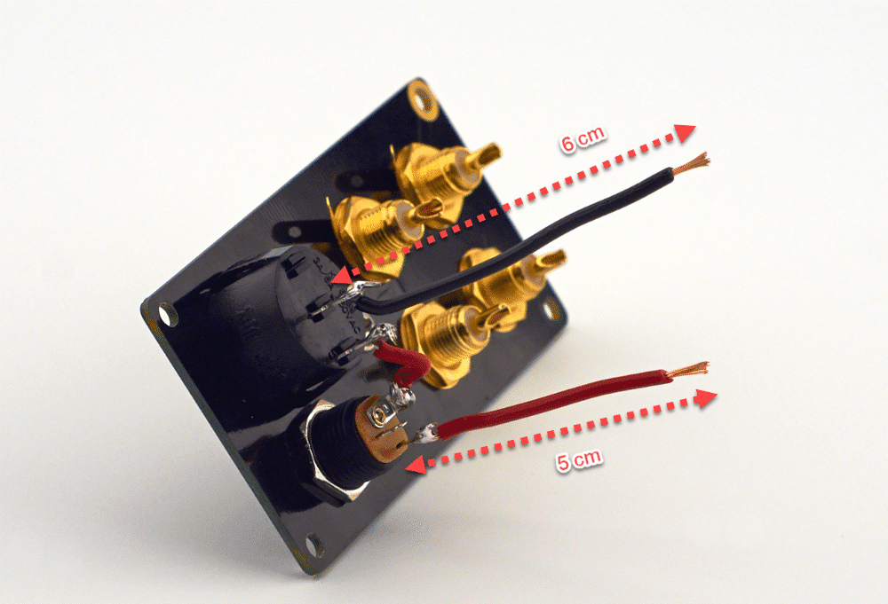
Cut two cables. Red = 5 cm and Black = 6 cm.
Strip ~0.5 cm from both ends of both cables, solder the shorter red cable to the bottom terminal on the power connector (the next one, clockwise from the L-shaped terminal).
Solder the black cable to the upper terminal of the power button, making sure not to overheat it. (Again, I've used 330 degrees C / 625 degrees F).
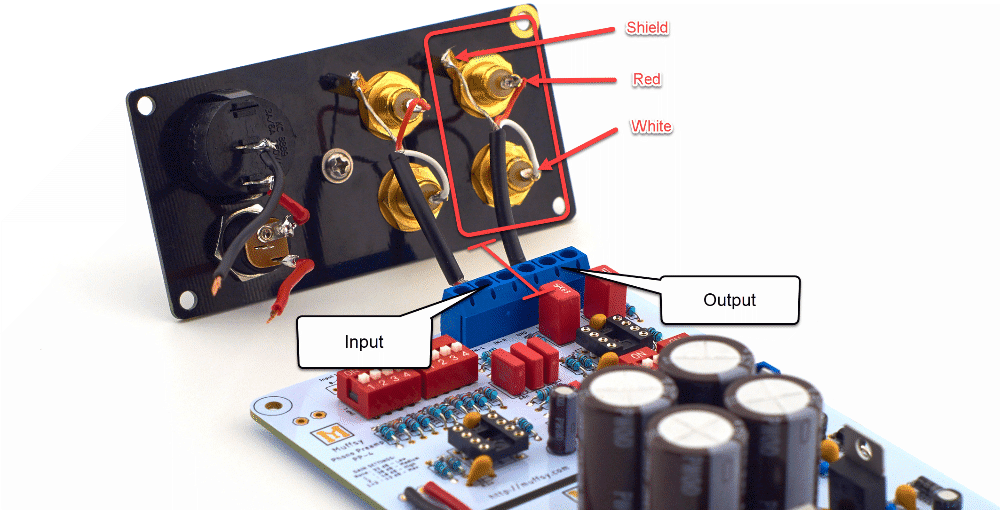
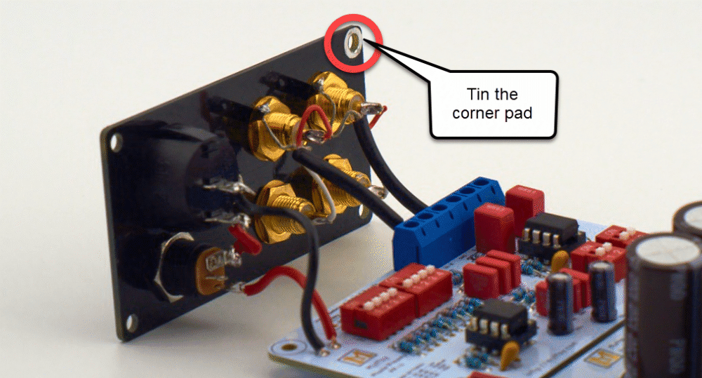
Solder the input and output signal cables to the back panel.
GND Terminal: Shield
Top RCA: Red
Bottom RCA: White
Solder all of them, aligned with the back panel as shown below:
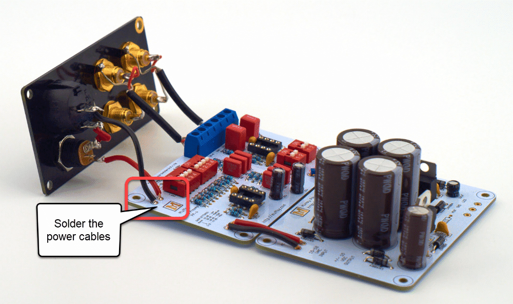
Solder the red and black power cables from the Muffsy Back Panel to the Muffsy Phono Preamp. It doesn't really matter which cable goes where, it does look nicer if it matches the cables from the Muffsy Phono Preamp to the Muffsy Power Supply though.
Finally, dab some solder on the corner pad on the Muffsy Back Panel. This will help ground and shield the entire phono stage later on.
Use just a small amount of solder and smear it around the pad.
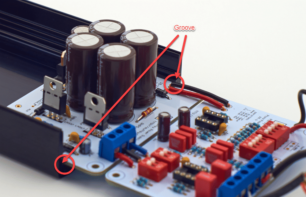
Step 13: Mount the Muffsy Phono Preamp in the B0905 Cabinet
Mounting the Muffsy Phono Preamp in the B0905 cabinet couldn't be easier. Just slide the boards into the grooves of the cabinet, starting with the Muffsy Power Supply.
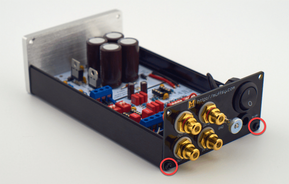
Screw the back panel in place, using the provided screws.
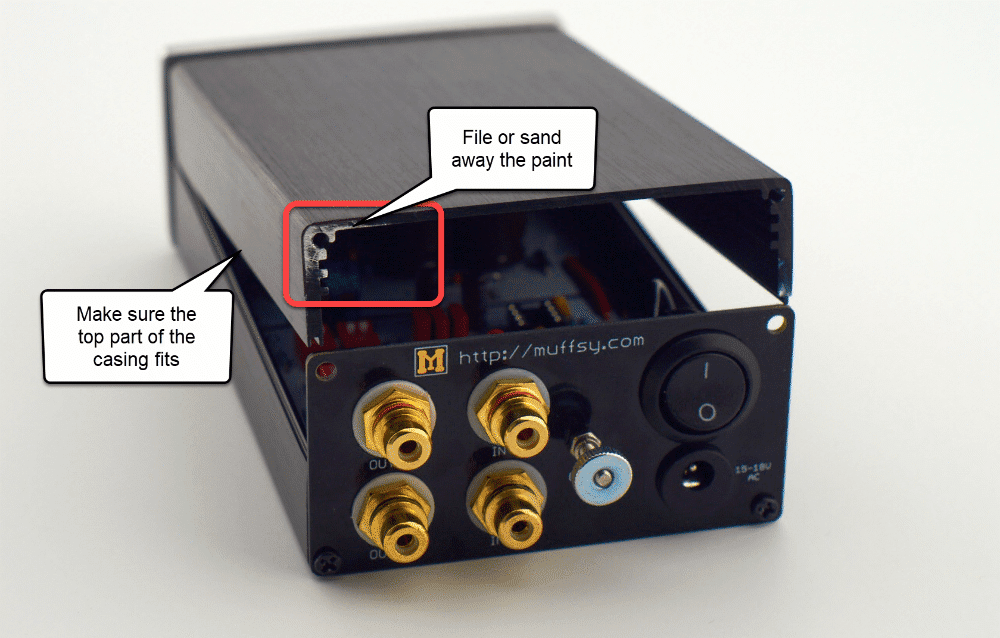
Test fit the upper part of the enclosure to see which way it fits. File or sand away the paint from the upper left corner.
This is where the tinned ground pad on the Muffsy Back Panel connects to the enclosure.
Step 13: Mount the Operational Amplifiers
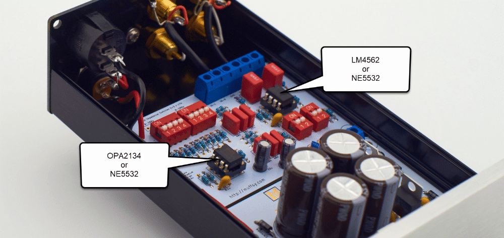
Whether you have ordered the OPA2134/LM4562, NE5532 or decided to use some other operational amplifiers, they have to be mounted in their sockets.
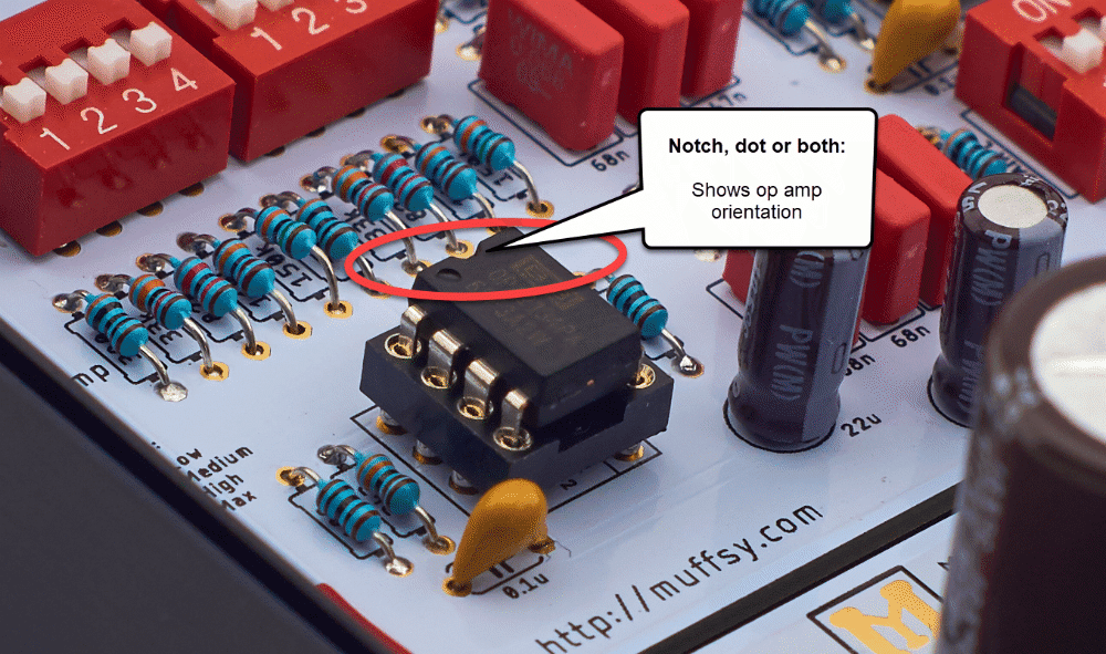
Carefully bend all the pins of the operational amplifiers inwards, so they are more straight. Insert them into their sockets, making sure they are oriented correctly. The notch on the operational amplifiers matches the notch on the sockets.
It does matter which operational amplifiers go where. For lowest noise and the best sound quality, follow the pictures below.
PLEASE NOTE: Make sure that you don't exceed the maximum voltage of your operational amplifiers. The Muffsy Power Supply delivers +/- 15 volts, which is fine for the op amps delivered with the kit. Other operational amplifiers can max out at +/-12 volts or even lower. (Have a look here if you need to change the Muffsy Power Supply's voltage.)
Wondering how to tell which way to orient the operational amplifiers? The markings on the board and on the DIL holders have a notch in them. Match this with a similar notch, dot, or both, on the operational amplifier.
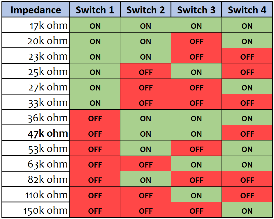
Step 14: Adjust the Input Impedance and Gain
The final step is to set the input impedance and amplification level on the Muffsy Phono Preamp.
Here's the recommended starting point for input impedance and gain:
Input Impedance Settings
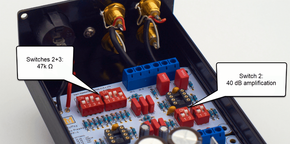
The switches to the top left, the ones with four settings, are used for setting the input impedance. The default setting is to set switches 2 and 3 to on, which will give you 47k ohms.
Please note that the input impedance switches must be set. Setting all the switches to OFF will make the Muffsy Phono Preamp sound awful. Do also make sure that the settings are identical on both switches.
With 47k ohms as a starting point, the general rules are:
- Higher values will give more treble
- Lower values will give less treble
Follow this chart to select the right input impedance:
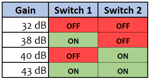
Selecting the Gain
The gain settings are controlled by the two switches on the bottom right, the ones with two settings.
The gain settings are really different volume presets. This allows you to match the cartridge on your turntable with your amplifier. Make sure that the settings are identical on both switches, or the volume will be different on the left and right channels.
Setting switch 1 to OFF, and switch 2 to ON will give you 40 dB of amplification, which is a good starting point. Go to a lower value if the volume is too high, and a higher value if the volume is too low. Use the table below to choose the right gain setting for your system:
Modifying the Gain
You can modify the gain by altering six resistors. Visit this page to learn more.

Troubleshooting
You may want to sanity check your new phono stage before powering it on. Or perhaps you can't get your Muffsy Phono Preamp to work?
Bring out your multimeter and do some tests:
Congratulations, You Have Built the Muffsy Phono Preamp
Here's a few parting words before you enjoy your new Muffsy MC Head Amp:
- The Muffsy Phono Preamp is only to be used with moving magnet (MM) or high output moving coil (HOMC) cartridges
- For low output moving coil (LOMC), pair your Muffsy Phono Preamp with the Muffsy MC Head Amp
- Connect the cables from your turntable to the input of the Muffsy Phono Preamp and make sure the ground cable is connected at both ends
- Tell all your friends, family, colleges and random strangers on the street about your Muffsy, and write about it on the forums you subscribe to
- An honest review on Tindie is always greatly appreciated. Do contact me first in case you have any complaints though, and we'll make sure your phono preamp is working to your satisfaction