Build the Muffsy Relay Input Selector 4
This kit is for sale on Tindie:
https://www.tindie.com/products/skrodahl/muffsy-relay-input-selector-kit/
The Muffsy Relay Input Selector kit comes with all on-board components, a rotational encoder and an IR receiver. These instructions will show you how to turn all this into a functional input selector for your stereo system, including how to easily decode and use the remote control of your choice.
You can view the schematics for the Muffsy products under the Modify It page.

Before You Begin Construction
PLEASE NOTE:
- Make sure you have time to construct the kit. If you are stressed, building the kit will not be very rewarding. And it often leads to mistakes.
- Familiarize yourself with the instructions before you start building the Muffsy Relay Input Selector.
- Take the time needed to double-check component values and placements.
- This kit contains components with a lot of pins. Make sure all pins are soldered.
- Wash your hands carefully afterwards if you're using leaded solder. Do not lick your fingers or touch any food items while working.
Illustrations Explained
The picture below is a larger version of your printed circuit board. For each step, this will be used to highlight which components you will be adding to the board.

You will also get a live view of where you are in the build process. It will show you what each component looks like, and present special information if needed.

Step 1: Check the Kit Contents
Before you start building, check that you have all components and familiarize yourself with the kit. Here's a list of the kit's contents:
| Quantity | Component |
|---|---|
| 1 | Muffsy Relay Input Selector Printed Circuit Board |
| 10 | Resistors, 1k ohms (extra resistors included for LEDs) |
| 5 | Diodes, 1N4004 |
| 6 | Transistors, PN2222A |
| 5 | Relays, Panasonic TQ2-5V |
| 2 | Stackable Headers, 19 Pins |
| 1 | ESP-32, NodeMCU-32S |
| 1 | Rotational Encoder, KY-040 |
| 1 | IR Receiver, VS1848B |
| 1 | Remote Control |
All resistors are 1/4W, metal film, 1% tolerance.
Note:
This high quality printed circuit board has plated-through holes. Do not attempt to drill the holes to make them larger, doing so will destroy the board. The four mount holes, one in each corner, may be drilled to size.
Step 2: Solder the Resistors
There is a total of six resistors, all with the same value of 1k ohms, that go onto the printed circuit board.
The resistors are bidirectional, meaning that you don't have to worry about which way they are oriented.

Insert the resistors, R1 to R6. Bend them on the backside of the board to make them stay in place. Solder the resistors and snip off the leads.


Step 3: Solder the Diodes
There are five diodes (1N4004) on the board, marked D1 to D5. The orientation matters, the black band on the board matches the silver band on the diodes.
Bend the leads appropriately and solder the diodes to the board. Snip the leads afterwards.

Again, notice the orientation of the diodes. They are all oriented the same way.
Step 4: Solder the Relays
There are five relays to solder, marked K1 to K5. Each relay has ten legs each, so make sure that every single leg has been soldered to the board.
The orientation of the relays is very important. Match the line to the left on the board markings with the line on the relays. Also, the text on the relays will be the right way up.

Tips:
- Use a piece of tape to hold the relays in place
- Solder two opposite corners of each relay first
- Reflow (melt) the solder in each corner with the soldering iron, pushing the relay to the board
- Solder the rest of the relay pins

Step 5: Solder the Transistors
There are six NPN transistors (PN2222A) on the board. These transistors act as switches for the 5V needed to activate the relays, since the ESP-32 board only outputs 3.3 volts.

The orientation of these transistors is given from the symbols on the board.
Here's how you mount the transistors:
- Bend back the middle leg slightly (left transistor, below)
- Place the transistor on the board, and push until the middle leg bends and the transistor is reasonably close to the board (right transistor, below)

Soldering the transistors:
- Solder only that bent middle leg first
- Turn the board around and check that the transistors haven't moved
- Melt the solder on the transistors that have moved, pushing them back into the board
- Solder the remaining legs and snip them off
.png "Muffsy Relay Input Selector - Transistors")
Step 6: Solder the Stackable Headers and ESP-32
The last component to go onto the board is the ESP-32 module that controls the relays.

Bring out the stackable headers, and take out the ESP-32 module from its ESD-protected bag.
Since the ESP-32's legs can be somewhat tilted, mount the stackable headers on the ESP-32 module. This will make sure that the pins of the ESP-32 module fits into the headers.

Now mount the ESP-32 and the headers to the board as shown below.
- Solder only the end pins of each stackable header
- Reflow (melt) the solder in each corner and push the ESP-32 module towards the board to make it flush with the PCB
- Solder all remaining thirty-six pins, make sure not to forget any of them

Step 7: Adding Controls and LED Status Lights
Creating a circuit board for the controls on this board would severely limit your choices. The options are too many and the front panel layouts are too personal. To get you going, the kit contains a rotational encoder and an IR receiver. These have to be wired manually to the board.
Twisting the rotational encoder will select inputs up and down. Pushing it will turn the input selector's power on and off.
The IR receiver lets you use a remote control. The example code has power on/off, inputs up/down, inputs directly by pushing the number buttons, and mute.
3V3 and GND Connections
You are going to need to connect several wires to GND and 3V3. Note that there are three GND pins on the board, they all work equally well. The connection drawings in steps 7.1 and 7.2 use the GND pads that make the pictures most readable, you can of course use any of them.

Connection Drawings
The connections have been separated into two different drawings for clarity. Combine the two to control the Muffsy Relay Input Selector and get status lights.
Step 7.1: Add Rotational Encoder and IR Receiver
To add the rotational encoder (KY-040) and the IR receiver (VS1848B), you'll need to know which pins to connect them to. The table below shows all pin assigments, the highlighted ones are the ones we need to hook up these accessories.
Pin Assignments - Input Controllers
| GPIO | PIN NAME | USED FOR |
|---|---|---|
| N/A | 3V3 | 3.3 volts power |
| N/A | GND | Power ground |
| 2 | IO2 | Power LED |
| 4 | IO4 | Mute LED |
| 5 | IO5 | Encoder SW |
| 12 | IO12 | Relay 2 (input B) |
| 16 | IO16 | Relay 1 (input A) |
| 17 | IO17 | Solid State Relay |
| 27 | IO27 | Relay 3 (input C) |
| 32 | IO32 | Relay 5 (mute) |
| 33 | IO33 | Relay 4 (input D) |
| 34 | IO34 | Encoder DT |
| 35 | IO35 | Encoder CLK |
| 36 | SVP | IR Receiver Pin 1 |
The remaining pins are all useable for LED status lights. But first, lets hook up the rotational encoder and the IR receiver.
Using the provided code, you'll need to connect the rotational encoder and IR receiver to the Muffsy Relay Input Selector board as shown below.

Step 7.2: Add LED Status Lights
The example code handles the following status LEDs:
- Power LED
- Mute LED (only when powered on)
- LED indicators for inputs 1 to 4
To help you along, here are the pins used for status LEDs in the example code.
Pin Assignments - Status LEDs
| GPIO | PIN NAME | USED FOR |
|---|---|---|
| 2 | IO2 | Power LED |
| 4 | IO4 | Mute LED |
| 5 | IO5 | Encoder SW |
| 12 | IO12 | Relay 2 (input B) |
| 16 | IO16 | Relay 1 (input A) |
| 17 | IO17 | Solid State Relay |
| 27 | IO27 | Relay 3 (input C) |
| 32 | IO32 | Relay 5 (mute) |
| 33 | IO33 | Relay 4 (input D) |
| 34 | IO34 | Encoder DT |
| 35 | IO35 | Encoder CLK |
| 36 | SVP | IR Receiver Pin 1 |
Here's how to connect the status LEDs to the Muffsy Relay Input Selector.
- Short LED pins/Black wires are GND
- Long LED pins/Colored wires go to the GPIO pins

Step 8: Muffsy Relay Input Selector - Signal Wiring
In its simplest configuration, you will have:
- four sets of RCA inputs connected to the input selector's inputs A to D
- One connection from input selector's the output to a preamplifier circuit
- One connection from the preamplifier circuit to the input selector's mute
- One connection from the input selector's mute to a set of output RCA connectors
If you plan to use any input specific preamplifiers, such as a phono preamp, place it between the RCA input and the input selector's input.
Should your phono preamp be in a separate enclosure, connect its output to one of the inputs below instead.

Some more tips:
- Isolate the RCA connectors (and any other connectors, such as a ground screw) from the back panel
- Power the Muffsy Relay Input Selector with it's own, separate, 5V DC power supply
- The SSR (solid state relay) connection can be used to turn on and off mains power connected through a solid state relay
(make sure not to turn off power to the Muffsy Relay Input Selector) - If you hook up your preamp cabinet to mains power, make sure to connect mains earth to the chassis
- MAINS POWER IS LETHAL - LEAVE ALL MAINS POWER WORK TO CERTIFIED PROFESSIONALS!
Step 9: Setup the Programming Enviroment
The ESP-32 used to control the Muffsy Relay Input Selector can be programmed in a range of different ways. If you'd like to use my code, the Arduino development tools are needed. They are available for Windows, Mac and Linux.
Install Drivers
The ESP32 board has a CP2102 USB to UART bridge, Windows drivers are available from Silicon Labs:
- Search for "espressif"
- Select "esp32 by Espressif Systems" and click "INSTALL":
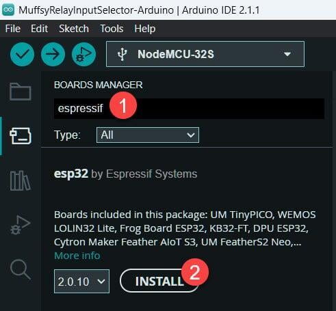
This is going to take some time, have patience and do not interrupt the installation
Step 10: IR Remote Control - Functions
The included IR remote control has a lot more buttons than what's programmed in the code provided by muffsy.com. This way you can have more buttons for customized functions if you write your own code.
Here are the functions that are enabled in the current code:

Step 11: Program the ESP-32
Programming the ESP-32 requires, besides the board installations in the Arduino IDE:
- The Arduino code for the Muffsy Relay Input Selector
- The Arduino library IRremote.h
Step 11.1: Download the Code from Github
The Arduino code for the Muffsy Relay Input Selector can be found on Github. Click on this link to download the code as a zip archive:
Unzip the downloaded file to find the following three folders:
- MuffsyRelayInputSelector-Arduino: Arduino Code
- MuffsyRelayInput4-Eagle: Eagle Project Files
If you're used to Git, here's the path to the repository:
Step 11.2: Connect the ESP32 board to Your Computer
Before continuing, you should connect the ESP32 board to your computer with a Micro-USB cable.
PLEASE NOTE:
The ESP-32 can only be powered by a single power source.
Do not power the ESP-32 through the PCB onboard power connection AND the USB cable at the same time,
as it might harm your ESP-32 module!
Remove the ESP-32 module from the Muffsy Relay Input Selector board if you're in doubt.
Step 11.3: Select the ESP32 Board in Arduino IDE
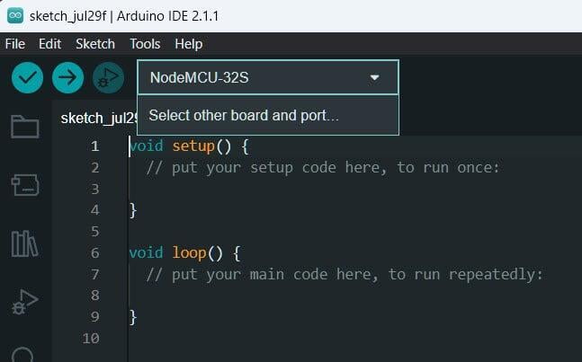
Click on the board selector in the Arduino IDE, unless it already says "NodeMCU-32S, and click on "Select other board and port...":
This will let you search through the available boards. Search for "mcu" and select "NodeMCU-32S". The port should be detected automatically
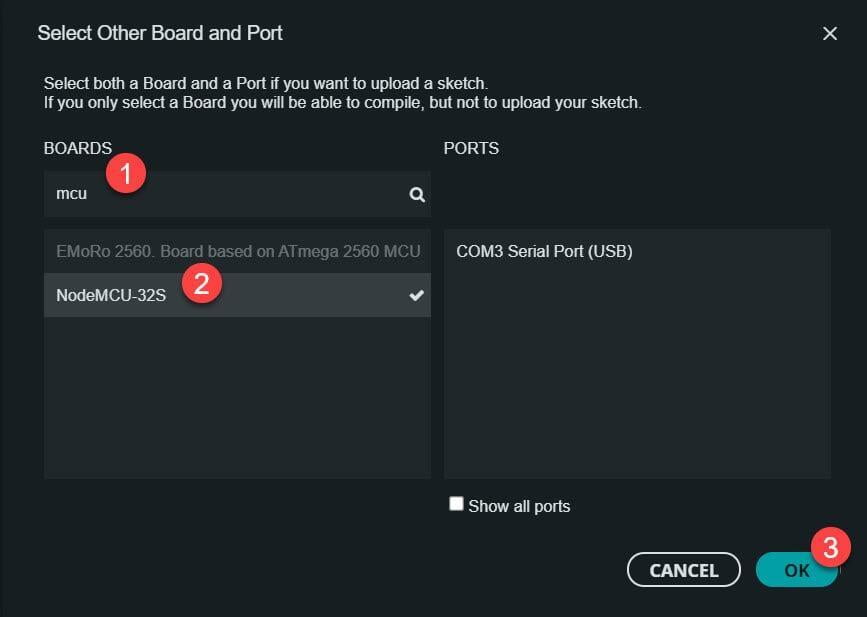
Note that the port on MacOS will start with /dev/cu.usbserial.
Step 11.4: Install the the Required Libraries in Arduino IDE
This library is needed in order to read the signals from your remote control.
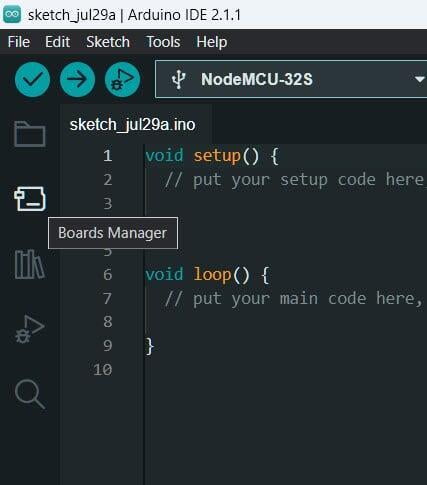
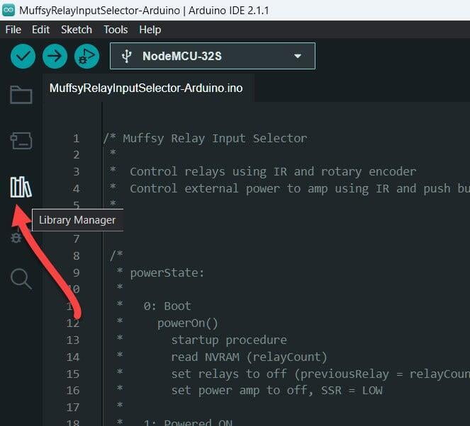
To install a library, click on the Library Manager icon:
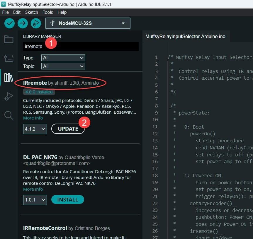
Search for the library "IRremote", select the one that is "by shirriff" and click install. If you already have IRRemote installed, you get the opportunity to update to the newer version.
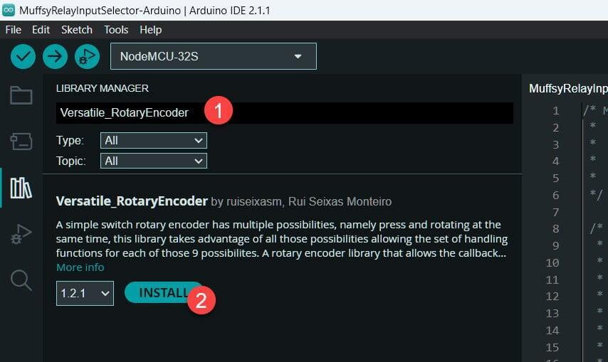
Search for the library "Versatile_RotaryEncoder", select the one by Rui Seixas and click install. If you already have this library installed, you can update it to the latest version.
Step 11.5: User Configurable Settings
There are a number of user configurable options in the beginning of the code. These are:
- IR Commands:
All the IR commands for the remote that comes with the input selector are defined here. You can use any IR remote you want. Everytime you push a button on any remote control, it is displayed in the Arduino IDE's serial console. Replace these values with your own if you want to use another remote.
See further below for instructions. - irRate:
Some IR remotes have a really fast repeat rate. Change this value to slow down the rate. - startupDelay:
When powering on the input selector, there is a delay when the circuit is muted. This is in case you have any equipment that can create pops when they start up. You can choose your own delay period by changing this value, or set it to 0 for no delay. - encDirection:
Change this value to reverse the rotation of the rotary encoder. - encPush:
The rotary encoder pushbutton uses short press for power on/off and long press for mute. Change this value to reverse this behavior. - rotRate:
Change this value to avoid skipping channels when turning the rotary encoder too fast. - enableSSR:Set to 1 to enable a Solid State Relay to control mains power to an amplifier module or similar. It is disabled by default, since working with mains power is dangerous.
Step 11.6: Install the Software to Your ESP32
Make sure you have performed these steps before installing the software to the ESP32 microcontroller. You can upload the code as many times as you want, for instance when you have made configuration changes.
- You have installed the Arduino IDE.
- You have installed the software package for ESP32-boards in the Arduino IDE.
- You have connected the board and selected it in the Arduino IDE.
- You have installed the IRRemote and Versatile_RotaryEncoder libraries.
- You have changed the user configurable settings, if needed.

Your Muffsy Relay Input Selector is now programmed and ready to use.
Optional: Configure another Remote Control
When the ESP32 is connected to your computer, it will display a lot of information in the Arduino IDE's Serial Monitor.
These are the messages shown when:
- The ESP32 has just booted, and
- I push the buttons 1, 2, 3 and 4 on a different remote control:
--- http://muffsy.com ---
The Muffsy Relay Input Selector has woken up!** Reading saved relay state from NVRAM: 1** Mute Relay turned ON** All input relays are turned OFF** Solid State Relay is turned OFF** Startup completed - waiting for Power ON-------------------------[http://muffsy.com]: Received IR code: 114[http://muffsy.com]: Received IR code: 38[http://muffsy.com]: Received IR code: 39[http://muffsy.com]: Received IR code: 115
Take note of the IR codes shown, and replace the values for oneButton, twoButton, threeButton and fourButton in the Arduino code with the new IR codes:
/** IR Commands** The following variables map all the buttons on the remote* control that comes with the Muffsy Input Selector.** Replace these commands with your own if you want to use another remote.** While connecting your Input Selector to the computer, it will display* any remote commands in the Arduiono IDE's Serial Monitor like this:** [http://muffsy.com]: Received IR code: <IR code of button pushed>** There are placeholder commands in the function irRemote{} for the buttons* 0 and 5 to 9 that serves as templates for your own IR routines*/#define zeroButton 13 // Placeholder command in the function irRemote{}, default: 13#define oneButton 114 // Input 1, default: 12#define twoButton 38 // Input 2, default: 24#define threeButton 39 // Input 3, default: 94#define fourButton 115 // Input 4, default: 8...
When you have replaced all default values with your own, you simply re-upload the code to the ESP32 as shown in the previous steps. You have now configured another remote control.
Optional: Modify the Arduino Code
The code is based on functions (blocks of code that can be called as "commands"), and it has a lot of comments that will help you if you want to modify the code.
Whether you're doing modifications, or writing the code from scratch, you need to take the physically reserved pins (the ones wired on the PCB) into account:
Physically Reserved Pins
| GPIO | PIN NAME | USED FOR |
|---|---|---|
| 2 | IO2 | Power LED |
| 12 | IO12 | Relay 2 (input B) |
| 16 | IO16 | Relay 1 (input A) |
| 17 | IO17 | Solid State Relay |
| 27 | IO27 | Relay 3 (input C) |
| 32 | IO32 | Relay 5 (mute) |
| 33 | IO33 | Relay 4 (input D) |
Great care has been taken to make sure the most usable ESP-32 pins are available. Both DACs are available, so are, I2C, SPI and most of the touch pins. Pins that are needed for programming the ESP, or pins that will prevent the ESP from booting, have not been used.
You'll also find that the pins used for the relays and the LED status lights don't output any signals during boot, so they will all be at their best behavior when turning the circuit on or off.